Author: Koen Faes, Research Team Leader, Belgian Welding Institute npo
Irene Kwee, Project Engineer, Belgian Welding Institute npo
Electromagnetic pulse welding is an innovative joining method which allows joining of dissimilar material combinations by using electromagnetic forces. This provides the advantage of combining desirable properties of different materials in one product, such as high strength, low weight or high corrosion resistance. The process duration is very short, requires only electricity and has no undesired by-products. In this publication, the weldability of copper tubes to steel rods and tubes has been investigated, which can be found, amongst others, in heating and cooling applications. The weld characterisation consisted of air leak testing, metallographic examination of the weld interface, and the measurement of the weld length and the deformation of the inner diameter of the internal steel tube. The aim was to investigate the effect of the welding parameters and the wall thickness of the internal steel tube on the weld quality. The majority of the tube-to-rod specimens contained a continuous and completely welded interface. For tube-to-tube specimens, a transition from a continuous weld interface to a discontinuous weld interface with non-welded zones occurred when the wall thickness of the inner steel tube decreased. Non-welded zones in certain specimens were caused by the radial deformation of the inner steel tube after the weld was created. The use of a polyurethane internal support for tube-to-tube specimens resulted in a significant improvement of the weld quality.
Introduction
Increasing requirements regarding weight and functionality of products in industry, leads to the necessity of joining dissimilar materials. However, disadvantages of traditional welding techniques have resulted in the development of innovative joining methods, such as the electromagnetic pulse technology, in which electromagnetic fields are used to join materials in an efficient way. This results in an improved lightweight hybrid design and a reduced environmental impact.
At the Belgian Welding Institute [1], the European H2020 research project “JOIN’EM” focuses on joining of aluminium to copper and copper to steel connections in both tubular and sheet configurations, through the electromagnetic pulse technology. These dissimilar connections are found in heating and cooling applications in different industrial sectors, such as the machine and equipment construction, automotive and transport, white goods, air-conditioning and high power electronics.
In particular, copper-to-steel tubular joints are a part of a refrigeration circuit of compressed air-dryers, which are used in cooling applications. A refrigerant gas/liquid flows at the inside, while the outside is exposed to the ambient conditions of an air-compressor room (up to 45°C). Moreover, such connections are also used as an inlet pipe of a compressed air-dryer, through which compressed air flows (approximately 35°C).
Currently, the Belgian company REFCO [2], specialized in bending, folding and brazing of copper, manually brazes copper tubes on to nickel-plated carbon-steel sleeves, using an acetylene torch. For the tubular connections which are part of the refrigeration circuit, the sleeve is fixed with a nut onto the refrigerant compressor or other components (see Figure 1). For the connections which are part of the inlet pipe, the resulting connection is brazed onto a carbon steel sleeve (see Figure 2). The main requirements are leak tightness of the joint during the lifetime of the air-dryer, which can amount up to 20 years, as well as no corrosion of the joint.
In both cases, electromagnetic pulse welding offers an alternative to brazing, as it is expected that it leads to a cost reduction due to the elimination of brazing filler materials and shortening of the production cycle. Moreover, improved joining quality due to increased automation is expected. The worker safety is also improved by eliminating hazardous substances, such as flame gas and brazing alloys.
In this article, the weldability of copper tubes to steel rods and tubes is examined, in order to identify the effect of the welding parameters and the wall thickness of the internal steel tube on the weld quality.
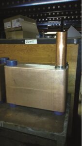
Figure 1: Copper tube brazed onto a carbon steel sleeve, as part of a refrigeration circuit of a compressed air-dryer.

Figure 2: Copper tube brazed onto a carbon-steel tube, as part of an inlet pipe of a compressed air-dryer.
Working principle of the electroMagnetic pulse welding process
A schematic overview of the electromagnetic pulse welding process and the electromagnetic equipment available at the Belgian Welding Institute is shown in Figure 3 and Figure 4, respectively. The set-up consists of a generator, a coil, afield shaper and the workpieces to be joined. A power supply is used to charge a capacitor bank. When the required amount of energy is stored in the capacitors, it is instantaneously released into the coil through a damped sinusoidal current. This primary discharge current induces a strong transient magnetic field inside the coil, which can be concentrated and intensified by a field shaper. This magnetic field in turn induces Eddy currents in the outer workpiece, named the flyer. This occurs according to Lenz’s law: the induced Eddy currents thus opposes the primary discharge current in the coil and prevents the magnetic field to diffuse through the flyer.
The flyer is accelerated because of the difference in magnetic field on the inside and outside of the flyer. This difference generates a magnetic pressure, which causes the accelerated flyer to impact with the parent at a high velocity. Depending on the impact angle and impact velocity, this creates a metal bond between the flyer and the parent material.
Important parameters that can be controlled and influence the weld quality are the charging voltage, the stand-off distance and the overlap distance between the tube and the field concentrator and between the flyer tube and the internal part. The charging voltage determines the amount of discharge energy provided to the process. The stand-off distance or gap is the initial distance between the workpieces and thus equals the distance that the flyer will travel prior to impacting onto the parent. The overlap length is the length the flyer tube overlaps with the field shaper.
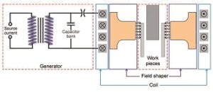
Figure 3: Schematic overview of the electromagnetic pulse welding process. [3]
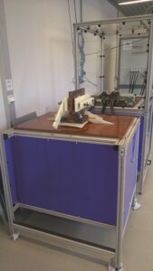
Figure 4: Electromagnetic welding equipment at the Belgian Welding Institute. [1]
Experimental study
Materials and specimens
Copper tubes were welded onto cold-worked carbon steel rods and tubes. The copper tubes had an outer diameter of 22, 22 mm and a wall thickness of 0,89 mm. The internal steel workpieces had an outer diameter such that the stand-off distance was varied between 1,0 mm, 1,5 mm and 2,0 mm. Four internal workpieces were used; a rod, and tubes with a wall thickness of 1,2 and 3 mm. The tube-to-tube specimen configuration is shown in Figure 5.
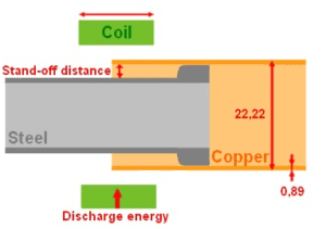
Figure 5: Tube-to-tube specimen configuration.
Weld characterisation
A leak test was performed during which the inside of the copper tube was subjected to an air pressure of 8 bar, as shown in Figure 6. The ends of the workpieces were sealed and the entire assembly was submerged into water. When air bubbles escaped from the weld location, either some severe imperfections were present, or there was no weld formed at all. The severity of the leakage was quantified by recording the pressure loss per unit of time.
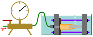
Figure 6: Set-up of the leak test.
In order to determine the actual cause of leaking welds or to assess the quality of leak-tight welds, metallographic examination was performed. Hereto, the specimens were cut in the longitudinal direction and subjected to metallographic preparations. The interfacial morphology, the weld length and, in case of tube-to-tube specimens, the decrease of the inner diameter of the internal steel tube were examined and related to the selected welding parameters.
RESULTS of the TUBULAR JOINTS WITHOUT SUPPORT
An example of an as-welded tube-to-tube joint is shown in Figure 7.

Figure 7: As-welded tube-to-tube joint.
Leak tightness
Leak tests on the tube-to-rod specimens revealed that all the joints with a stand-off distance of 1 mm had failed. The tube-to-rod specimens produced with a stand-off distance of 1, 5 mm and 2 mm passed the leak test, which indicated that these were likely sound welds. In contrast, tube-to-tube specimens produced at all stand-off distances exhibited poor leak tightness. The tube-to-tube specimens with a wall thickness of the internal steel tubes of 3 mm however showed a better leak tightness than specimens with a wall thickness of the internal steel tubes of 1 and 2 mm.
Interfacial morphology
An example of a metallographic cross section indicating the decrease of the inner diameter of a welded tube-to-tube specimen is shown in Figure 8a (wall thickness of the internal steel tube: 3 mm). The black line at the interface might suggest that no weld was obtained. However, this can be explained by difficulties in the specimen preparation process of multi-material joints, especially if materials with significant differences in strength and hardness are concerned. In case of copper and steel, material removal will always be slightly more distinct for the softer copper, so that the surface of copper and steel after polishing are not exactly on the same level. In case of moderate magnifications, the shift in the surface level appeared as a dark line, which can easily be misinterpreted as a gap in-between the copper flyer and steel target. If however higher magnifications are used, the shift of the surface level becomes detectable, because the focus has to be adapted in order to obtain a clear picture of the flyer or target surface. In Figure 8b, a detail of the weld interface shows that a wavy bond has been formed between the copper and steel.

Figure 8: (a): Metallographic cross-section of a tube-to-tube specimen with a wall thickness of the internal steel tube of 3 mm (b) Detail of the wavy interface eat the copper-steel interface.
Two possible theories concerning the bonding mechanism in electromagnetic pulse welding have been proposed in literature [4]. One assumes that solid-state mixing of the two materials takes place, while the other assumes that bonding is caused by local melting and solidifying on a submicron scale. Usually, the most successful welds show a wavy pattern between the two welded materials, as illustrated in Figure 8b. This is believed to be the result of the jetting phenomenon, which is the creation of a jet of material in front of the collision point, that is subsequently expulsed due to its high speed [3].
Figure 9 illustrates the different phenomena which can take place at the copper-steel weld interface. The high cooling rate can give rise to shrinkage cracks, while cavitation during melting can give rise to porosities. Intermixing of the materials can occur, resulting in interfacial layers. Under certain conditions, this can give rise to the formation of intermetallic phases. These phases should be limited, as they are likely detrimental to the weld quality due to its possible brittleness. Below a certain thickness, the intermetallic phases rarely contains defects, and when a wavy interface is present, these intermetallics are formed at the crests of the waves in melt pockets [5].

Figure 9: Interfacial layers, cracks and porosities in a copper-steel weld interface.
Figure 10 shows that different copper-steel weld interfaces were present: (a) a continuous interface with a completely welded zone, (b) a continuous interface with a welded zone containing porosities at the centre, (c) a discontinuous interface with a welded zone at the beginning and the end, (d) a discontinuous interface with a welded zone at the end and a non-welded zone at the beginning and in the centre, (e) no welded interface.
In general, the transition from a continuous weld interface to a discontinuous weld interface with non-welded zones takes place when the wall thickness of the internal steel tube decreases. Hence, a continuous weld interface with a completely welded zone is usually observed for tube-to-rod specimens and tube-to-tube specimens with a wall thickness of the internal steel tube of 3 mm. A discontinuous weld interface is detected for the majority of the tube-to-tube specimens with a wall thickness of the internal steel tube of 1 mm. A possible hypothesis is that fracture of the weld can likely be attributed to the high welding speed, which can significantly exceed the deformation rate of the internal steel tube in the radial direction. The weld is therefore formed prior to the initiation of the deformation of the internal steel tube in the radial direction, and hence the diameter of the internal steel tube only starts decreasing after the weld has been formed [6]. Based on this, it is possible that the created weld was not sufficiently strong to withstand the forces caused by the deformation of the inner tube and hence failure occurred at the weld interface. An example of such a defective tube-to-tube specimen is shown in Figure 11a, compared to a similar pattern in a tube-to-rod specimen in Figure 11b, which does not exhibit any radial deformation nor defects.

Figure 10: Different copper-steel weld interfaces.

Figure 11: Microstructure of (a) a defective tube-to-tube specimen (b) a successful tube-to-rod specimen.
Moreover, a correlation between the weld interface and the stand-off distance has been identified. Tube-to-tube specimens produced with a stand-off distance of 2 mm were either long and continuous, or failed catastrophically due to cracks at the weld interface. In contrast, tube-to-tube specimensproduced with a smaller stand-off distance of 1,5 and 1 mm, only contained short discontinuous welds. Often, two short welded zones were present, separated by a non-welded region. This non-welded region showed the presence of large, almost continuous, and fractured interfacial pockets. Specimens produced with the same welding parameters but in the tube-to-rod configuration often showed an increase of interfacial pockets near the middle of the welded zone. Most likely, it is this region that failed for tube-to-tube specimens due to the deformation of the internal steel tube after welding, as it is very brittle and the porosities are prone to crack initiation. The region with an increased amount of interfacial layers can be explained by the local temperature increase during welding [4].
Effect of welding parameters on weld quality
The decrease of the inner diameter of the internal steel tubes for the 3 different wall thicknesses is shown in Figure 12. The effect of the stand-off distance at a fixed discharge energy of 20 kJ is illustrated in Figure 12a, whereas the effect of the discharge energy at a fixed stand-off distance of 2 mm is shown in Figure 12b.
A higher stand-off distance resulted in a larger decrease of the inner diameter, as the flyer can accelerate over a longer distance. This assumes that the flyer has not reached its deceleration point yet over a distance of 2 mm. Also a higher discharge energy contributed to a larger decrease of the inner diameter, due to more energy being available for deformation.
In general, the inner diameter of the internal steel tube decreased for a smaller wall thickness of the internal steel tube, due to the smaller resistance against deformation. Moreover, the decrease of the inner diameter of tube-to-tube specimens with a wall thickness of 1 mm was more than twice the amount, compared to the specimens with wall thickness of 2 and 3 mm. This amount of deformation is most likely unacceptable, as it causes a decrease of up to 52% in diameter. This equals losing 3/4 of the inner tube area, which is very critical in for example fluid applications.

Figure 12: Decrease of the inner diameter of the internal steel tube as a function of the (a) stand-off distance (fixed discharge energy: 20 kJ) (b) discharge energy (fixed stand-off distance: 2 mm)
The weld length of the tube-to-rod specimens and tube-to-tube specimens with the 3 different wall thicknesses of the internal steel tube is shown in Figure 13.The effect of the stand-off distance at a fixed discharge energy of 20 kJ is illustrated in Figure 13a, whereas the effect of the discharge energy for a fixed stand-off distance of 2 mm is shown in Figure 13b.
In particular, the stand-off distance significantly influences the weld length: a larger stand-off distance of 2 mm usually resulted in the longest weld length, as already observed in the metallographic examination. This indicated that 2 mm is a sufficient distance over which the copper flyer tube can accelerate and reach the required impact velocity for weld formation. In contrast, the shorter weld lengths measured for welds produced with a stand-off distance of 1,5 and 1 mm might indicate that these distances were too small for the copper flyer tube to reach a sufficient velocity. At a medium discharge energy of19 kJ, the weld length either reached a minimum or maximum, but in general no clear correlation between the weld length and the discharge energy has been identified.
The longest weld lengths were obtained for tube-to-rod specimens and for tube-to-tube specimens with a large wall thickness of the internal steel tube, as observed in the metallographic examination of the weld interface (see Figure 10).

Figure 13: Weld length as a function of the (a) stand-off distance (fixed discharge energy: 20 kJ) (b) discharge energy (fixed stand-off distance: 2 mm).
RESULTS of the TUBULAR JOINTS WITHSUPPORT
Because it was observed that the weld quality decreased for tube-to-tube specimens with a wall thickness of the internal steel tube of 1 mm, the same welding experiments were repeated with the use of a polyurethane support within the internal steel tube.
Figure 14 illustrates the metallographic cross sections of tube-to-tube specimens without (a) and with internal support (b). These indicate the decrease of the inner diameter of the internal steel tube. Both specimens were produced with a stand-off distance of 2 mm and a discharge energy of 20 kJ.
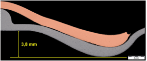
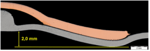
Figure 14: Metallographic cross section of tube-to-tube specimens with a wall thickness of the internal steel tube of 1 mm. Illustration of the reduction of the inner diameter of the internal steel tube (a) produced without an internal support (b) produced with an internal support.
Figure 15 compares the decrease of the inner diameter of the internal steel tubes for tube-to-tube welds with a wall thickness of 1 mm, produced with and without an internal support. The evolution of this decrease is illustrated as a function of the stand-off distance, with a fixed discharge energy of 20 kJ (see Figure 15a) and as a function of the discharge energy, with a fixed stand-off distance of 2 mm (see Figure 15b).
The use of an internal support leads to a decrease of the reduction of the inner diameter of the internal steel tubes with a factor up to 3,4. Also, the range of values of the decrease of the inner radius (10- 15%) for supported tube-to-tube specimens with a wall thickness of 1 mm was similar to the values obtained for unsupported tube-to-tube specimens with a wall thickness of 2and 3 mm. Moreover, the decrease of the inner diameter for supported tube-to-tube specimens, exhibited a smaller variation and were less dependent on the variation of the gap and the discharge energy.

Figure 15: Decrease of the inner diameter of the internal steel tube as a function of the (a) stand-off distance (fixed discharge energy: 20 kJ) (b) discharge energy (fixed stand-off distance: 2 mm).
Figure 16 compares the weld length for tube-to-tube welds with a wall thickness of 1 mm, produced with and without an internal support. The evolution of the weld length is illustrated as a function of the stand-off distance, with a fixed discharge energy of 20 kJ (see Figure 16a) and as a function of the discharge energy, with a fixed stand-off distance of 2 mm (see Figure 16b).
The use of an internal support also resulted in an increase of the weld length with a factor up to 4. However, the variance of the values of the weld length in case of supported tube-to-tube specimens remained. Likewise as for unsupported tube-to-tube specimens, a small increase of the weld length was recorded for supported tube-to-tube specimens produced with a larger stand-off distance. Again no clear correlation between the weld length and the discharge energy was identified.

Figure 16: Weld length as a function of the (a) stand-off distance (fixed discharge energy: 20 kJ) (b) discharge energy (fixed stand-off distance: 2 mm).
Conclusions
The weldability of copper tubes to steel rods and tubes has been investigated. The effect of the welding parameters and the wall thickness of the internal steel tube on the interfacial weld morphology, the weld length and the deformation of the internal steel tube has been identified.
- For tube-to-rod specimens and unsupported tube-to-tube specimens, the longest weld lengths were achieved for the largest stand-off distance of 2 mm and the largest wall thickness of 3 mm of the internal steel tube. The smallest reduction of the inner diameter of the internal steel tube was obtained at the smallest discharge energy of 18 kJ, the smallest stand-off distance of 1 mm and the largest wall thickness of 3 mm.
- The majority of the tube-to-rod specimens exhibited a continuous weld interface with a completely welded interface. For tube-to-tube specimens, the transition from a continuous weld interface to a discontinuous weld interface with non-welded zones took place when the wall thickness of the internal steel tube decreased. This failure was most likely caused by the radial deformation of the internal steel tube after the weld was created.
- The stand-off distance plays a significant role in determining the weld quality: at the largest stand-off distance of 2 mm, the copper flyer tube was likely still accelerating and had not yet reached its maximum impact velocity. Hence, this explained the longest weld length, as well as the largest reduction of the inner diameter of the internal steel tube. The effect of the stand-off distance was also reflected in the interfacial weld morphology. Welds produced with a stand-off distance of 2 mm were both long and continuous, or failed catastrophically due to cracks at the weld interface. In contrast, welds achieved with a smaller stand-off distance contained short discontinuous welded zones.
- The use of a polyurethane internal support for tube-to-tube specimens with a wall thickness of 1 mm of the internal steel tube resulted in a reduction of the decrease of the inner diameter of the internal steel tube with a factor of 3,4 and an increase of the weld length by a factor up to 4.
1 Acknowledgements
The presented results were achieved within the project joining of copper to aluminium by Electro Magnetic fields – “JOIN’EM”. This project is funded by the European Union within the frame of the Horizon 2020 research and innovation program under Grant Agreement No. 677660.

For more information regarding the possibilities and applications of the electromagnetic pulse technology, please contact:
Belgian Welding Institute
Mr. Koen FAES
Koen.Faes@bil-ibs.be
References
- Belgian Welding Institute. Available online: http://www.bil-ibs.be/en
- Available online: http://www.refco.be/en
- Sapanathan, R. N. Raoelison, N. Buiron, and M. Rachik, “Magnetic Pulse Welding: An Innovative Joining Technology for Similar and Dissimilar Metal Pairs,” in Joining Technologies, M. Ishak, Ed. InTech, 2016.
- Stern, V. Shribman, A. Ben-Artzy, and M. Aizenshtein, “Interface Phenomena and Bonding Mechanism in Magnetic Pulse Welding,” J. of Material Eng and Perform, vol. 23, no. 10, pp. 3449–3458, Oct. 2014.
- Kudiyarasan and S. A. Vendan, “Magnetic Pulse Welding of Two Dissimilar Materials with Various Combinations Adopted in Nuclear Applications,” Indian Journal of Science and Technology, vol. 8, no. 36, Dec. 2015.
- Ben-Artzy, A. Stern, N. Frage, V. Shribman, and O. Sadot, “Wave formation mechanism in magnetic pulse welding,” International Journal of Impact Engineering, vol. 37, no. 4, pp. 397–404, Apr. 2010.


