


Dr.T.Senthilkumar
DEAN & Professor
Department of Automobile Engineering
University College of Engineering
BIT Campus, Anna University Tiruchirappalli, Tamil Nadu, India

Dr.S.Siddharth
Associate Professor(G)
Department of Mechanical Engineering,
PSN College of Engineering and Technology,
Melathediyoor, Tirunelveli, 627451, Tamil Nadu, India
Abstract – In this paper, nondestructive evaluation of friction stir spot welded dissimilar joints were conducted. Dissimilar combinations of aluminum alloy Al 5083 – H111, copper C10100 and SPCC steel joints were examined using radiographic testing. The joints were inspected for macro and micro defects, and the weld quality was ascertained. The important process parameters and its feasible limits for good quality and defect free joints were evaluated.
Keywords – Nondestructive testing, friction stir spot welding, dissimilar joints, radiographic testing.
INTRODUCTION
Joining of dissimilar materials are difficult due to differences in mechanical and metallurgical properties they possess. Friction Stir Spot Welding (FSSW), a linear variant of Friction Stir Welding, is a solid state material joining process which can be used effectively for dissimilar spot joining processes. It is being used to join dissimilar materials like aluminium, copper and steel. FSSW is a three step process involving plunging, stirring and drawing out. A non-consumable rotating tool is used for inducing frictional heat into the weld zone [1].
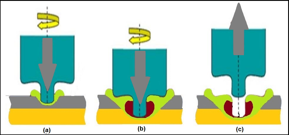
Fig 1. FSSW process (a) plunging, (b) stirring and (c) drawing out
Out of the various process parameters of the friction stir spot welding process, three important process parameters which determines the weld quality was found to be tool rotational speed, dwell time and plunge depth [2]. FSSW is more advantageous and eradicates most of the problems associated with conventional spot joining processes such as mechanically riveted joints, toggled and clinched joints [3, 4]. It is a three step process. First step is plunging (Fig. 1 (a)), where a hard non-consumable rotating tool is plunged into the work pieces to induce frictional stir in the weld region. Next is stirring (Fig. 1 (b)), a definite period of time for which the tool is made to remain at the plunged position to induce frictional heat and soften the materials. Third is the drawing out process (Fig. 1 (c)) where the tool is withdrawn from the weld zone to allow the weld spot to cool and thus forming a FSSW joint.
Nondestructive testing procedures are commercially used for large quantity inspection of joint quality, without inducing changes in post weld quality. In production process industries the requirement of fast pace inspection without compromise in quality of the quality checked products desire nondestructive testing. Joon-Tae Yoo et al., used radiographic testing for studying the joint quality of friction stir welded Al 2195-T8 joints. The effect of travel speed and tool rotation speed on the joint quality were ascertained [5].The FSSW joints can have a probe hole left after the drawing out process, which acts as a corrosion and crack initiation region in the weld spot, thereby reducing the joint strength. In automotive applications, the reach of paint till the bottom of the spot does not occur [6]. Thus the defect goes unattended.
The importance of nondestructive evaluation in inspection of welds was described quantitatively by Farley et al., [7]
Probability of failures in welding = Flaw occurrence probability x probability of missing of the flaw detection by non-destructive evaluation techniques x growth probability of the flaw
Using conventional and phased array ultrasonic nondestructive testing procedures, the quality of friction stir welded AA 5083 aluminium alloys had been evaluated [8]. From the study of previous literatures, it was found that nondestructive evaluation of dissimilar friction stir spot welds were very less. Thus in this investigation, nondestructive evaluation of dissimilar friction stir spot joints of aluminium, copper and steel have been conducted using radiographic testing.
2.0 EXPERIMENTS
2.1 Base material and Friction stir spot welding procedure
For this study, Al 5083 – H111 aluminium (Al) commercial alloy, C10100 oxygen free copper and SPCC steel sheets, all having 1.5 mm thickness were chosen. The specimens were sized to 100 mm length and 30 mm breadth. FSSW joints were made with an overlap of 30 mm, placing the softer material on the top of the lap configuration. Three sets of experiments were conducted. First combination with Al5083- C10100 and second Al5083-SPCC, both with Al on the top. Third combination was made with C10100-SPCC and in this, Cu was made the top plate. The purpose of placing the softer material on the top was to increase the life of the non-consumable tool. The chemical combination of the base materials are given in Table 1. The important mechanical properties are given in Table 2.
Table 1. Nominal chemical composition of the base materials (wt. %).
| Al 5083 | Si | Mg | Mn | Fe | Cr | Cu | Zn | Ti | Al |
| 0.4 | 4.0-4.9 | 0.4-1.0 | 0.4 | 0.25 | 0.1 | 0.25 | 0.15 | balance | |
| SPCC | C | Mn | P | S | Si | Cu | Zn | Ti | Fe |
| 0.25 | 0.6 | 0.035 | 0.04 | 0.10 | 0.2 | – | 0.05 | balance | |
| C10100 | Pb | Sn | S | Fe | Zn | O | P | As | Cu |
| 0.003 | 0.002 | 0.004 | 0.004 | 0.003 | 0.002 | 0.002 | 0.002 | balance |
Table 2. Important mechanical properties of the base materials
| Material | Yield Strength(M Pa) | Tensile strength(M Pa) | Elongation(%) | Hardness(HV) |
| Al 5083 | 145 | 290 | 22 | 87 |
| SPCC | 185 | 340 | 41 | 185 |
| C10100 | 275 | 310 | 20 | 75 |
For manufacturing the non-consumable tool, H13 tool grade steel hardened to 53 HRC was chosen.
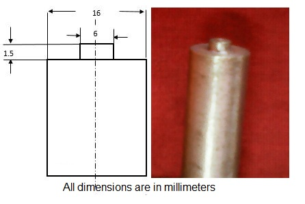
Fig. 2. FSSW Tool nomenclature
The tool was made with a cylindrical profile, with a shoulder diameter of 16 mm, cylindrical pin probe of 6 mm diameter, 1.5 mm long. The tool geometry is chosen so as to ensure proper plunge and stir during the FSSW process. The schematic representation of FSSW process is shown in Fig. 3 (a) and the vertical milling machine used for making the joints are shown in Fig. 3 (b).
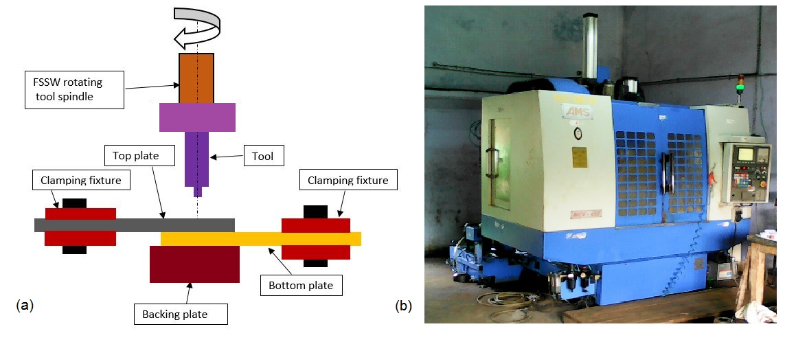
Fig. 3 (a) Schematic diagram of FSSW process (b) FSSW equipment
2.2 Identification of process parameters and fabrication of the jointsOut of the various process parameters of FSSW process, three important parameters that affect the weld quality were chosen based on previous literature study. Tool rotational speed in rpm (R), plunge depth in mm (D) and dwell time in seconds (T) were the important process parameters found to influence the joint strength [3]. FSSW experiments were conducted with process parameters given in Table 3. FSSW joints with three combinations Al/Cu, Al/SPCC, Cu/SPCC were conducted with a constant feed rate of the spindle at 12 mm/min. The axial force was maintained at 1000 N for all the joints. Thirty two joints were made in each combination. A few of the joints fabricated are shown in Fig. 4.
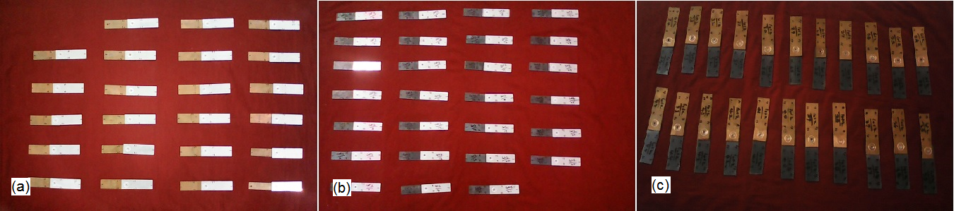
Fig. 4. FSSW joints (a) Al 5083- C10100, (b) Al5083-SPCC, (c) C10100-SPCC
Table 3 –Process parameter values
| Exp No | COMBINATIONS | ||||||||
| Al5083 – C10100 | Al5083 – SPCC | C10100-SPCC | |||||||
| R | D | T | R | D | T | R | D | T | |
| 1 | 800 | 1.8 | 10 | 1080 | 1.4 | 9 | 898 | 1.4 | 10 |
| 2 | 963 | 1.8 | 10 | 1080 | 2.2 | 9 | 1102 | 1.4 | 10 |
| 3 | 1137 | 1.8 | 10 | 1420 | 1.4 | 9 | 1102 | 2.3 | 9 |
| 4 | 1137 | 1.8 | 15 | 1420 | 2.4 | 9 | 1102 | 2.4 | 8 |
| 5 | 963 | 1 | 10 | 142 | 2.4 | 14 | 898 | 1.6 | 10 |
| 6 | 1137 | 2.2 | 10 | 1080 | 1.6 | 9 | 1102 | 1.6 | 10 |
| 7 | 1137 | 2.6 | 10 | 1420 | 1.6 | 9 | 800 | 1.6 | 15 |
| 8 | 963 | 2.6 | 11 | 1080 | 1.4 | 11 | 898 | 1.4 | 12 |
| 9 | 963 | 1.8 | 12 | 1080 | 1 | 11 | 1102 | 1.4 | 12 |
| 10 | 1137 | 1.8 | 12 | 1080 | 1.2 | 16 | 800 | 1.4 | 15 |
| 11 | 963 | 2.2 | 12 | 1420 | 1.4 | 11 | 1250 | 1.4 | 13 |
| 12 | 1500 | 2.2 | 12 | 1080 | 1.6 | 11 | 898 | 1.6 | 12 |
| 13 | 1137 | 2.2 | 18 | 1420 | 1.6 | 11 | 1102 | 1.6 | 12 |
| 14 | 1137 | 2.2 | 12 | 1000 | 1.5 | 10 | 850 | 1.5 | 11 |
| 15 | 875 | 2 | 11 | 1500 | 1.5 | 10 | 1000 | 1.4 | 16 |
| 16 | 875 | 2.1 | 18 | 1600 | 1.6 | 11 | 1150 | 1.5 | 11 |
| 17 | 1425 | 2 | 11 | 1550 | 1.5 | 10 | 1000 | 1.3 | 11 |
| 18 | 1150 | 1.6 | 11 | 1250 | 1.3 | 10 | 1300 | 1.6 | 15 |
| 19 | 1150 | 2.4 | 11 | 1250 | 1.7 | 10 | 1350 | 1.5 | 15 |
| 20 | 1150 | 2 | 9 | 1250 | 1.5 | 8 | 1000 | 1.7 | 11 |
| 21 | 1150 | 2.6 | 9 | 1300 | 1.9 | 10 | 1000 | 1.5 | 9 |
| 22 | 1150 | 2 | 13 | 1250 | 1.5 | 12 | 898 | 1.5 | 9 |
| 23 | 1150 | 2 | 11 | 1250 | 1.5 | 10 | 1000 | 1.5 | 13 |
| 24 | 1150 | 2 | 11 | 1250 | 1.8 | 14 | 1000 | 1.5 | 11 |
| 25 | 1150 | 2.8 | 11 | 1250 | 2.1 | 10 | 898 | 1.9 | 12 |
| 26 | 1150 | 2 | 11 | 1250 | 1.5 | 10 | 1000 | 1.5 | 11 |
| 27 | 1150 | 2 | 11 | 1250 | 1.5 | 10 | 1250 | 1.5 | 12 |
| 28 | 1150 | 1.2 | 17 | 1300 | 2.2 | 11 | 1000 | 1.5 | 11 |
| 29 | 1150 | 2 | 11 | 1250 | 1.5 | 10 | 1000 | 1.5 | 11 |
| 30 | 1400 | 2 | 11 | 1250 | 1.5 | 10 | 1275 | 1.5 | 16 |
| 31 | 1450 | 2 | 11 | 125 | 2.3 | 12 | 1000 | 1.5 | 11 |
| 32 | 1150 | 2 | 11 | 1250 | 1.5 | 10 | 1000 | 1.5 | 11 |
| Tool rotational speed R – in rpm, Plunge depth D in mm, Dwell time T in seconds | |||||||||
3.0 RESULTS AND DISCUSSION
In automotive and other structural applications, small cracks formed in the interface of the spot welds may become a source for origination of defects. Reach of paint till the center of the joint spot by normal painting methods does not happen always and so detection of defects is very important for prevention of long term damage. In this investigation, radiographic testing was used for detection of defects in the spot welds.
Fig. 5. Radiographic testing equipment
The radiographic testing equipment is shown in Fig. 5. The testing setup is made by calculating the source from camera distance. The size of a single specimen was 170 mm by 30 mm. Using radiographic films of size 4 inches by 8 inches, five specimens were tested per experiment. Source to film distance (SFD) was calculated using formula
µg = {source(s) x thickness (t)} / {SFD – thickness (t)}
From the specifications of camera, diameter of the camera aperture (d) = 2.7 mm and length (l) = 1.8 mm.
Using Pythagoras theorem s2 = d2 + l2
The total thickness was 3 mm. Since the job thickness was less than 25mm value of µg was chosen as 0.5. Iridium 192 was the radiographic wave source used. The name of the film used was Iridium 192 source.
Exposure time = {FF x 2t/hvt x (SFD)2 x 60} / {CI x RHM x 10002}
FF is film factor constant. In this investigation, a medium film was used. So the value of FF was chosen to be 1.8. (hvt) – Half value thickness was chosen to be 12.5. CI – is curie number. The curie strength on the day of the testing was 15.38 curie. RHM – roentgen hour per millirem value for iridium 192 is taken as 0.5. Optimum film exposure time of 45 seconds was given for each tests. After exposure, the film is developed. The developer room illumination was maintained less than 30 lux. First it was soaked in a developer for a soaking time of 5 minutes. The constitution of developer solution was 20% alkaline and 80% water. Then the film was soaked in a stop bath for 1 minute. The constitution of stop bath was 2% acetic acid and 98% water. After this process, the film is soaked in fixer for 1 minute. Fixer consisted of 20% sodium thiosulphate and 80% water. Then it was washed in running water and washed in soap oil and allowed to dry. The room temperature during development was maintained between 18˚C to 24˚C. The developed radiographic films were vied at an illumination of 1000 lux for finding defects and cracks at the joints surfaces.
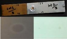
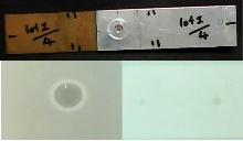
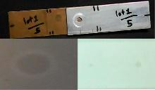
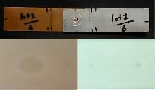
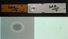
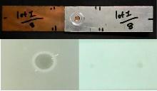
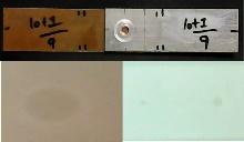
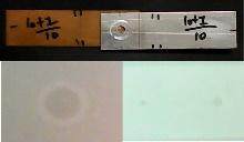
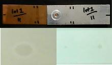
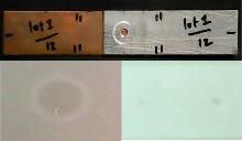
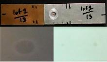
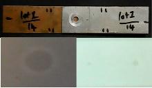
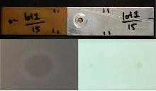
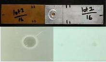
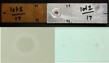
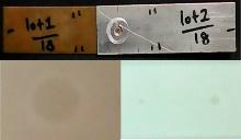
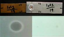
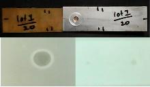
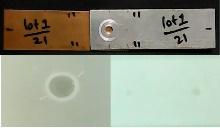
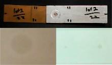
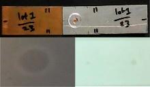
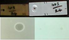
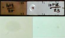
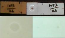
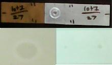
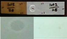
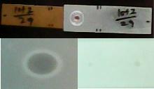
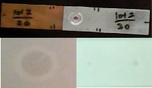
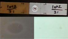
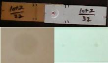
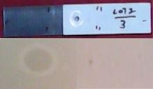
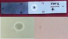
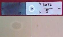
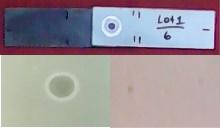
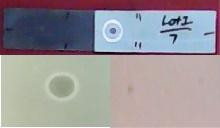
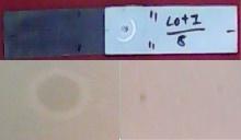
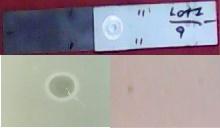
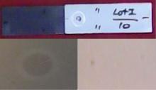
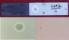
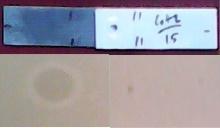
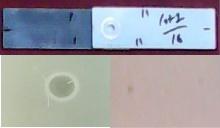
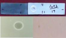
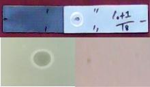
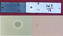
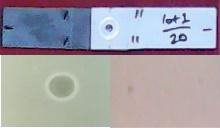
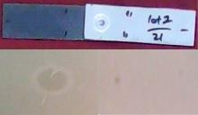
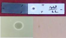
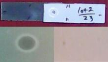
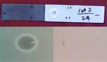
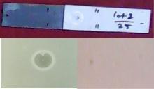
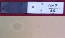
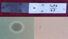
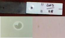
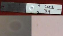
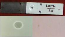
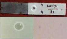
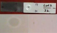
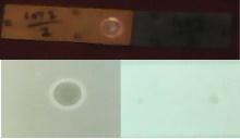
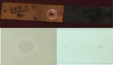
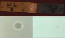
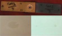
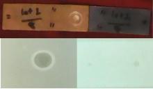
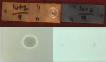
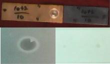
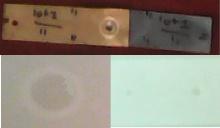
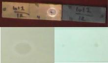
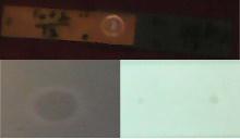
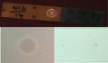
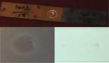
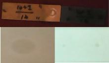
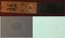
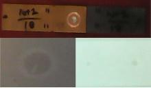
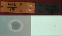
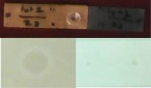
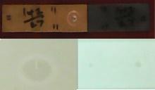
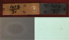
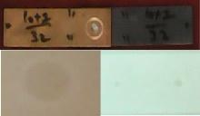
The joints fabricated were subjected to radiographic testing and the results are tabulated. The defects were measured in accordance with standard defect detection criteria and the cracks were identified. A radiography test sample is show in Fig. 5.Radiographic evaluation results of Al5083/C10100 joints are given in Table 4, that of Al5083/SPCC are given in Table 5, and that of C10100/SPCC joints are given in Table 6.
Fig. 6. Radiographic test specimen, compared with standard defect size.
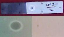
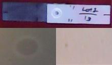
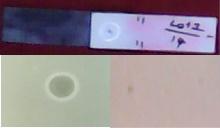
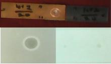
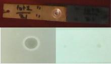
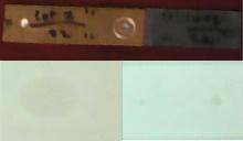
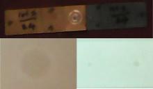
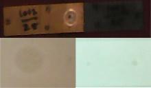
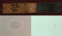
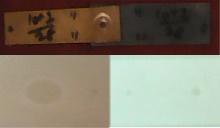
Table 4 – Radiographic test results of Al5083 – C10100 FSSW joints
 |  |  |  |  |  |
| 1) Defective | 2) No defect | 3) No defect | 4) Defective | 5) No defect | 6) No defect |
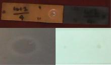
 |  |  |  |  |  |
| 7) Defective | 8) Defective | 9) No defect | 10) No defect | 11) No defect | 12) Defective |
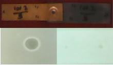
 |  |  |  |  |  |
| 13) Defective | 14) No defect | 15) No defect | 16) Defective | 17) No defect | 18) No defect |
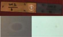
 |  |  |  |  |  |
| 19) No defect | 20) No defect | 21) Defective | 22) No defect | 23) No defect | 24) No defect |
 |  |  |  |  |  |
| 25) Defective | 26) No defect | 27) No defect | 28) Defective | 29) No defect | 30) Defective |
 |  | ||||
| 31) Defective | 32) No defect |
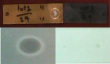
Table 5 – Radiographic test results of Al5083 – SPCC FSSW joints
 |  |  |  |  |  |
| 1) No defect | 2) Defective | 3) No defect | 4) Defective | 5) Defective | 6) No defect |
 |  |  |  |  |  |
| 7) No defect | 8) No defect | 9) Defective | 10) No defect | 11) No defect | 12) No defect |
 |  |  |  |  |  |
| 13) No defect | 14) No defect | 15) No defect | 16) Defective | 17) Defective | 18) No defect |
 |  |  |  |  |  |
| 19) No defect | 20) No defect | 21) Defective | 22) No defect | 23) No defect | 24) Defective |
 |  |  |  |  |  |
| 25) Defective | 26) No defect | 27) No defect | 28) Defective | 29) No defect | 30) No defect |
 |  | ||||
| 31) Defective | 32) No defect |
Nondestructive evaluation using radiographic testing involves detection, interpretation and evaluation which are the three fundamental steps for defect identification and interpretation.
The defects act as source for crack initiation and increases the possibility of corrosion to occur. In the first combination of Al5083/C10100 joints, out of 32 spot welds, by radiographic inspection, 12 joints were found to be defective. In the second set of FSSW combinations of Al5083/SPCC joints, 11 joints were found to have cracks and defects.
In the third set of combinations involving C10100/ SPCC joints 11 were found defective. The values of process parameters of the defective joints were analyzed with the defect free joints for obtaining the feasible limits for high quality joints, under experimental conditions used in this investigation. Thus the upper and lower limits of the important process parameters such as tool rotational speed in rpm, plunge depth in mm, dwell time in seconds were found and are presented in Table – 7.
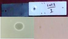
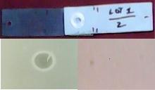
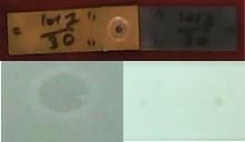
Table 6 – Radiographic test results of C10100 – SPCC FSSW joints
 |  |  |  |  |  |
| 1) No defect | 2) No defect | 3) Defective | 4) Defective | 5) No defect | 6) No defect |
 |  |  |  |  |  |
| 7) Defective | 8) No defect | 9) No defect | 10) Defective | 11) Defective | 12) No defect |
 |  |  |  |  |  |
| 13) Defective | 14) No defect | 15) Defective | 16) No defect | 17) No defect | 18) Defective |
 |  |  |  |  |  |
| 19) Defective | 20) No defect | 21) No defect | 22) Defective | 23) No defect | 24) No defect |
 |  |  |  |  |  |
| 25) Defective | 26) No defect | 27) Defective | 28) No defect | 29) No defect | 30) Defective |
 |  | ||||
| 31) No defect | 32) No defect |
Table – 7 – Limits of process parameters for the FSSW joints
| Parameters | Notation | Unit | Al5083/C10100 | Al5083/SPCC | C10100/SPCC | ||||||
| Low | Middle | High | Low | Middle | High | Low | Middle | High | |||
| Tool Rotational Speed | RS | rpm | 875 | 1150 | 1425 | 1000 | 1250 | 1500 | 850 | 1000 | 1150 |
| Plunge Depth | D | mm | 1.6 | 2 | 2.4 | 1.3 | 1.5 | 1.7 | 1.3 | 1.5 | 1.7 |
| Dwell time | T | seconds | 9 | 11 | 13 | 8 | 10 | 12 | 9 | 11 | 13 |
It was observed that below the lower limit of tool rotational speed, the welds were improper due to lack of proper heat generation. Above the upper limit of the tool rotational speeds, excessive heat caused deformations and cracks in the joints. Plunge depth below the lower limit caused improper penetration and lack of proper weld. Above the upper limit of the plunge depth, sheet tearing were observed. Below the lower limit of the dwell time, the joint were not strong due to lack of softening of the materials for the required duration. Dwell times beyond the upper limit caused excessive heat generation and pull out of the top plates resulting in defective joints.
CONCLUSIONS
Thus, in this investigation, the quality of dissimilar friction stir spot joints were evaluated using radiographic technique. The defects of dissimilar joints of Al5083/ C10100, Al 5083/ SPCC and C10100/SPCC made under various process parameters were evaluated using Iridium 192 source. Very small surface cracks, voids, spatters were effectively identified using radiographic technique. By analyzing the process parameters of defect free and defective joints, the feasible limits for good quality joints were obtained.
REFERENCES
[1] Harsha Badarinarayan, ‘Fundamentals of friction stir spot welding’, PhD thesis, Missouri University of Science And Technology, United State, 2009.
[2] Lakshminarayanan A.K., Annamalai V.E., Elangovan K., “Identification of optimum friction stir spot welding process parameters controlling the properties of low carbon automotive steel joints”, Journal of Materials Research and Technology, 2015, Vol 4(3), pp. 262–272
[3] Malafaia AMS, Milan MT, Oliveira MF, Spinelli D., ”Fatigue behavior of friction stir spot welding and riveted joints in an Al alloy”, Procedia Eng, 2010, Vol. 2(1), pp. 1815–1821.
[4] Briskham P, Blundell N, Han L, Hewitt R, Young K, Boomer D., “Comparison of self-pierce riveting, resistance spot welding and spot friction joining for aluminium automotive sheet”, SAE Int Tech pap 2006, Paper No: 2006-01-0774.
[5] Joon-Tae Yooa, Jong-Hoon Yoona , Kyung-Ju Mina, “Effect of Friction Stir Welding Process Parameters on Mechanical Properties and Macro Structure of Al-Li alloy”, Procedia Manufacturing, 2015, Vol. 2, pp. 325 – 330.
[6]. Y. Uematsu , K. Tokaji , Y.Tozaki, T. Kurita, S. Murata, “Effect of re-filling probe hole on tensile failure and fatigue behavior of friction stir spot welded joints in Al–Mg–Si alloy”, International Journal for Fatigue, 2008, Vol. 30, pp. 1956–1966.
[7] Farley J.M., Thompson J.L., Dikstra B.J., “Nondestructive Testing to avoid weld failures: A review”, J.D. Harrison (Ed.) International Conference on Weld Failures, The Welding Institute, London, England, 1988.
[8] Vidya Joshi, Krishnan Balasubramainam and Raghu V Prakash, “Study of defects in friction welded AA5083 by radiography, ultrasonic and phased array ultrasonic technique”, Proc. National. Seminar on Nondestructive Evaluation, NDE 2011, 2011.
LIST OF FIGURES
Fig 1. FSSW process (a) plunging, (b) stirring and (c) drawing out.
Fig. 2. FSSW Tool nomenclature
Fig. 3 (a) Schematic diagram of FSSW process (b) FSSW equipment
Fig. 4. FSSW joints (a) Al 5083- C10100, (b) Al5083-SPCC, (c) C10100-SPCC
Fig. 5. Radiographic testing equipment.
Fig. 6. Radiographic test specimen, compared with standard defect size.
LIST OF TABLES
Table 1. Nominal chemical composition of the base materials (wt. %).
Table 2. Important mechanical properties of the base materials.
Table 3 –Process parameter values
Table 4 – Radiographic test results of Al5083 – C10100 FSSW joints
Table 5 – Radiographic test results of Al5083 – SPCC FSSW joints
Table 6 – Radiographic test results of C10100 – SPCC FSSW joints
Table – 7 – Limits of process parameters for the FSSW joints


