


P. Goswami, P. Eng, IWE, Welding & Metallurgical Specialist, Ontario, Canada.
Welding repair on aged and service exposed pressure equipment and piping and other components are always a challenge to welding engineers. The rationale is very simple. Various mechanical properties degrade over aging and service exposure. Material properties in aged components are always inferior that brand new components. Post Weld Heat Treatment is the Ultimate option to reduce weld residual stresses, improve ductility, notch toughness, and reduce hardness. However, complete PWHT for in-service components are not always feasible due size and location of components, extent of repair, and material property issues after many years of service related exposures and many other constraints.
Weld repair by temper bead technique is an attractive option for in-service repair of some grade of common and popular Ferritic pressure vessel steels. Execution of this technique in field should be ‘precise’ and ‘very systematic’. This technique was originally developed for Nuclear Utilities and adopted by the ASME Nuclear Design Codes (Sec-III) and in service Inspection Code-Sec –XI and later adopted by other weld repair codes e.g. NBIC for non-nuclear applications. Due to the different design stringencies and acceptance considerations, multiple variations of Temper bead repairs techniques had been developed over last 30 years.
This paper summarizes various recommended techniques and relative pros and cons of all, as well with special emphasis on various factors related to this technique.
Introduction to Temper Bead WeldingTemper bead welding technique was originally developed as an alternative to Post Weld Heat Treatment (PWHT) welds mandated by design and construction codes, thus to reduce as-welded HAZ hardness. Temper bead welding technique is one of the most important repair welding methods for large structures for which it is difficult to perform the specified post weld heat treatment. The temper bead welding has been specifically developed to refine the coarse grained HAZ in the parent metal by the judicious positioning of weld beads and control of heat input.
The definition and technique:
According to The American Society of Mechanical Engineers (ASME), the definition of Temper bead technique is as follows:-
“Temper bead welding: a weld bead placed at a specific location in or at the surface of a weld for the purpose of affecting the metallurgical properties of the heat‐affected zone or previously deposited weld metal. The bead may be above, flush with, or below the surrounding base metal surface. If above the base metal surface, the beads may cover all or only part of the weld deposit and may or may not be removed following welding.”
A word of Caution: Temper bead welding technique is never a substitute for post weld heat treatment in circumstances where operating conditions require a substantial reduction in residual stress levels and meeting other requirements. This heat treatment aims to improve locally the fracture toughness and reduce the peak hardness within the HAZ.
- Governing Codes and Standards
Non-Nuclear:
National Bard Inspection Code (NBIC) is the most common code followed for repair and alteration by non-nuclear industries, such as Electric Utilities, Oil and Gas Industries. As per NBIC Under certain conditions, post weld heat treatment, in accordance with the original code of construction, may be inadvisable or impractical. Alternative methods for PWHT may be used in such instances. One of the recommended alternatives is Temper Bead Welding Technique. NBIC Part 3, Clauses 2.5.3.2 thru 2.5.3.5 are methods in which the welding procedure requires the use of a temper-bead welding technique.
Nuclear:
ASME Sec-III, NB-4622.9 allows limited weld repairs on P-No. 1 and P-No. 3 material, without PWHT or after the final PWHT, provided it is impossible or impractical to post weld heat treat the area after repair, and provided further requirements according to this code are met.
- Metallurgical Principles (Microstructural Changes) Behind Weld & HAZ
Fig-1 shows the various microstructural changes occurring during a typical arc welding process. This helps to understand what takes place in the HAZ due to welding and post weld heat treatment, or temper bead welding. The reference here is temperature ranges vs the resultant microstructure with respect to the iron-carbon phase diagram. These microstructural changes are valid for many grades of conventional Ferritic Steels (Carbon & Creep Resisting) used in the used in construction of power /petrochemical & refinery plants.
As per documented evidences for Cr-Mo creep resistant steels formation of a wider intercritical zone had led to Type-IV creep cracking in service. It is important to narrow the intercritical zones well, as to get the significant width of subcritical zone to have effective tempering done for the base metal, with controlled heat input and correct weld bead placements.
- Various Temper Bead Welding Techniques
During temper bead welding, the heat input, preheat and weld bead sequence are closely controlled to:-
- a) Limit heat input and pre-heat to avoid excessive grain coarsening of the ‘coarse grained’ HAZ of the first weld layer;
- b) Increase heat input by a set amount for the second weld layer to grain refine the coarse grained HAZ of the underlying first weld layer;
- c) Overlap the placement of successive weld beads to produce grain refinement of the adjacent bead.
Multiple temper bead welding techniques have been developed over the past 30 years. However, this paper discusses only the techniques popular with the industries.
- a) Half Bead Technique
- b) Controlled Deposition Technique
All techniques have a common goal of tempering the coarse grained HAZ (Ref Fig-1) in the parent metal. The methods by which the weld beads are deposited vary on chosen technique as discussed below.
- Half Bead Technique (Adopted in ASME Sec-III, Nuclear Codes)
Originally developed for use in the nuclear industry, but this technique has since become widely popular for repairs of high temperature piping, headers and turbine casings in conventional power plant.
The SMAW technique is used and employs a series of increasing diameter electrodes, starting with 2.5 mm, then 3.2 mm and finishing with 4.0 mm electrodes. The increasing diameters provide a gradual and sufficient increase in heat input for gradual tempering from the first to the third layer.
The area to be repaired should be cleaned and preheated to a temperature commensurate with the material and thickness (typically >150oC), and a buttering technique used as a first layer with 2.5 mm electrodes. The use of 2.5 mm electrodes is to produce a small, shallow heat affected zone.
The second step is to remove approximately half of the welded layer by grinding.
The third step is the deposition of a second layer using 3.2 mm electrodes. This effectively re-transforms the coarse-grained heat affected zone and first layer.
The remaining steps are the deposition of third and subsequent layers using 4.0 mm electrodes with further MINOR grinding after each deposited layer as required. Each subsequent layer transforms and tempers the layers beneath it.
The disadvantage of the technique is that a lot of accurate grinding is required. This is time consuming and if too much material is removed from the first layer, the effects of the re- transformation are not successful. As a result this technique has now lost favor in Non-Nuclear Industries.
- Controlled Deposition Technique
This technique was developed to repair C-Mo steels in conventional fossil fueled power plants where creep embrittlement and re-heat cracking were potential problems during repair. It uses SMAW technique, and uses strictly controlled ratios of heat input between one weld layer and the next. The heat input for the second layer is 1.3 to 1.8 times higher than for the first layer, and is designed to produce grain refinement and tempering in the original heat affected zone. The ratios need to be experimentally verified for each material to be welded.
The increase in heat input should be 30 to 70% for each subsequent layer, and for SMAW, increasing the electrode size by one size whilst keeping the welding technique the same generally achieves this.
It is not necessary in production to use exactly the same heat input as in the procedure test, but the ratio between layers must remain the same.
Part of the weld metal and HAZ of the first bead is re-melted by the second bead. How much is re-melted depends on the overlap, but typically, a 50% overlap is the aim. The temper bead technique usually involves completing the first layer first.
The heat input for the second layer runs is increased so that the heat re-melts some of the first layer but re-transforms the coarse-grained area of the HAZ while tempering the inter-critical region. Extreme care is needed with placement of the final run. The third layer is a repeat of the second layer with increased heat input.
- Qualification of Temper bead Welding Procedure
Temper-bead welding procedure qualification nomenclature is defined in Section IX of the ASME Boiler and Pressure Vessel Code. Typically, this technique minimizes heat input of the initial beads, thus limiting heat beyond the weld heat-affected zone (HAZ) of the base metal. Heat input shall be increased for successive beads in accordance with the rules of QW-290 for temper bead welding in ASME Section IX.
The six sub-clauses under this section provide the requirements for procedure qualification requirements, restrictions, essential and non- essential variables, test coupon preparation and testing and in-process repair welding. Additionally, sub-clause QW-290.6 provides supplementary qualification requirements for the welders who will be carrying out the work.
ASME Sec-IX is most commonly followed code for welding procedure and performance qualification. QW-290 addresses all the relevant clauses for Temper bead welding. When the applicable Code Section specifies the use of this paragraph for temper bead welding, QW-2 90.1 through QW-290.6 shall apply. The appropriate clauses are as follows:-
- QW-290.1 Basic Qualification and Upgrading Existing WPSs
- QW-290.2 Welding Process Restrictions
- QW-290.3 Variables for Temper Bead Welding Qualifications
- Table QW-290.4 Welding Variables for Temper Bead Procedure Qualification
- QW-290.5 Test Coupon Preparation and Testing
- QW-290.6 In-Process Repair Welding
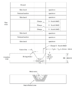
The test specimen layout as shown in Sec-III, NB is extracted under Fig-3 below.
In order to assess the metallurgical effectiveness of the temper bead welding procedure on the materials being repaired required the following four supplementary tests are generally applied:
1) Microstructural assessment of Weld and HAZ
2) Hardness Testing
3) Charpy Vee Notch Impact Testing
4) Bend Test
In order to determine the effectiveness of the temper bead welding procedure, it will be necessary to compare the temper bead HAZ results with:
- a) The same results obtained from the conventional welding procedure qualification test after the traditional post weld heat treatment;
- b) The same test results obtained from the conventional welding procedure without post weld heat treatment.
Both comparisons are required to determine if the applied temper bead welding technique provides the required results.
- Qualification of Temper Bead Welders
In addition to the usual welder qualification requirements of ASME Section IX, it is necessary for welders to complete a supplementary proficiency demonstration. This demonstration mimics the actual welding to be carried out with a sufficient amount of welding to show competency.
The complexities of most temper bead welding techniques require the welder to be supervised by a competent person for the duration of the welding. Weld toe tempering can be achieved by a competent welder in a satisfactory manner without full time supervision.
- Conclusions
Temper bead is a very specialized welding technique, which is used in lieu of Post Weld Heat Treatment. Hence upon application, conformance to Code of Construction/Repair, Metallurgical factors related to base metals/ welds all have to be met so as to prevent occurrences of failures upon service. Following key factors are essential before or while implementation of any Temper bead weld repair on aged components.
- Planning,
- WPS Qualification,
- Training of Personnel Involved,
- Welder or Welding Operator Qualification or Proficiency,
- Demonstration,
- Inspection & Records/Documentation.
7. References:-
- National Bard Inspection Code (NBIC)-2011, Part-3
- ASME BPV Code, Sec-III
- Welding Technology Institute of Australis (WTIA) publication, TGN-PE-02,Temper Bead Welding, Rev0,1 March 2006.
ASME, BPV Code-Sec-IX
Fig 1: Iron–carbonphasediagramshowingthetransitionpointsrelatingtoaweldHAZ.(Ref-3)

Note: During welding, there can be up to four sub-zones within the HAZ created according to the maximum temperature reached and the duration of time at that temperature.
These sub-zones are:
- Sub-critical: 650 – 723oC
- Inter-critical: 723 – 900oC
- Fine Grain: 900 – 1000oC
- Coarse Grain >1000oC < melting point.
Formation of these sub-zones is determined by the transformation characteristics of the steel. The dashed lines linking the iron-carbon phase diagram on the left to the HAZ sub-zones indicates the transformation taking place during the welding process.
Fig 2: Illustration from ASME Sec-III NB-4623.1 on the technique adopted for temper bead repair in nuclear construction. (Ref-2)

Fig 3: Illustration on the technique adopted for temper bead repair in non-nuclear construction. (Ref-3)

Fig 4: Welding Procedure Qualification Test Plate Layout, extracted from ASME Sec-III, NB, in accordance with ASME Sec-IX
(Ref-2 & 4)


