


Ehsanullah Khan, National Expert – Welding & Cutting, Air Liquide India
Shielding atmospheres in MAG/GMAW processes for un-alloyed carbon steels may contain various CO2 contents, ranging from low oxidizing (ISO 14175: M20) to highly oxidizing (up to ISO 14175: C1) shielding atmospheres.
The content of CO2 shows an important influence on the various drop transfer modes and affects spatter rate, weld and pool appeal, fume and gas emissions but also productivity and surface defects.
Using recent high speed video examinations, the presentation will show the different arc modes possible for various shielding compositions and the corresponding process windows allowing high productivity and quality welds for the existing arc generator technologies.
Based on the findings, a comprehensive and optimized range of MAG/GMAW shielding gases for un-alloyed carbon steels and mild steels allows responding to nearly all requests in a quality fabrication of metallic goods, provided that the shielding gases are supplied with a stringent quality specification from a cylinder supply to a liquid on-site mixture.
Introduction
Benefits of Ar/CO2 mixtures on MAG welding process
Shielding atmospheres in MAG/GMA welding processes for un-alloyed carbon steels may contain various CO2 contents, ranging from low oxidizing (ISO 14175: M20) to highly oxidizing shielding atmospheres (up to ISO 14175: C1).
CO2 additions into argon start to stabilize the arc at rather low contents (e.g. above 0.1% CO2), in percentage levels they secure the weld soundness.
To achieve a good X-ray quality of the welded carbon steel, CO2 contents above 5% are necessary. The higher the CO2 content, the broader the penetrations shape at similar penetration depth.
Figure 1: Finger shape penetration.
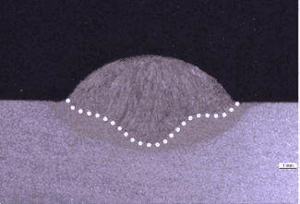
Figure 2: Rounded penetration.

Low CO2 containing gases show a finger shaped penetration when higher amounts show a widened, rounded one. CO2 additions show with higher CO2 content higher flexibility to fit up tolerances. This is mainly due to higher arc voltages, which widen the arc and bridge so gaps.
Such bigger and wider arc plume burns off easily oil and grease which occasionally may contaminate the steel surface.
The first CO2 mixtures appeared in the early 50’s with mixtures containing between 25% and 18% CO2. Different options had been taken by Japan, USA or Europe. The reason of these different options was empirical and based mainly on habits and use of the starting companies.
These 3 different types of mixtures are today the reference mixtures for the normative work in those countries, JIS-ISO for Japan, AWS-ISO in US and EN-ISO for Europe. They are referenced also in construction codes and pressure vessel codes.
During the past decades, a large number of binary mixtures was created by the industry ranging today from 8% to 50% CO2 content. The latter was introduced for on-shore /off-shore welding of steel piping in the oil and gas industry. Here the gas shroud -rather heavier than air- helps to compensate the wind draft which may disturb the shielding during the process.
However, when reaching CO2 contents higher than 20%, the important arc instabilities lead to heavy spattering, as well as to heavy fume emission rates. High CO2 contents also lead to higher over weld issues as well as spattering, affecting the productivity and the overall costs of the welded pieces.
Why all these compositions?
The welding generators showed during the same 4 decades the evolution from a standard diode driven generator with natural drop transfer modes to software monitored, forced drop transfers.
Figure 3: Increased drop transfer know how.
The forced drop transfer was used to bridge the critical globular mode area by pulsing, reducing spattering and improving overall weld quality.
The last generation of software controlled generators is driving a forced arc mode in short circuiting and pulsing. When diode driven generators accepted all types of shielding gases (adapting the inductance by loop setting versus CO2 content) pulsing needs high argon contents as such pulsed generators are built with transistors not over-passing peak currents of 450A.
(The first pulsed equipments were sold in the late 70’s, being an additional pulsing devise, added to the standard diode generator.) In the end it became necessary to get a new and better knowledge about drop transfer modes and behaviors in MAG welding of carbon steels, in order to master the process data.
Drop transfer know-how 1
During the diode/ transistor phase, only the short circuiting, globular and spray mode (streaming transfer), included rotating spray (Air Liquide 1964), was definitely known and understood.
Figure 4: Operating range for a M21 and C1 shielding gas.

Figure 5: Classic metal transfer; Ref.1.

The drop transfer know how 1993
In 1993 Prof. Ushio published the first information regarding the arc modes which can be detected by laboratory means.
Figure 6: Drop transfer modes as ref.1.
These arc modes, not known before, are separating the globular area into 2 domains:
– The Globular drop transfer
– Repelled globular transfer
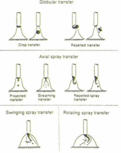
The globular drop transfer shows an irregular drop size, irregular weld surface and spattering. Repelled drop transfer leads to heavy spattering and adherent spatters. Spray modes are separated into 5 different domains:
– Projected spray: drops at rather regular size are projected into the weld puddle.
– Streaming transfer is an extremely regular and stable drop transfer, the one an experienced welder is able to set up easily.
– Repelled spray is a mode where the liquid droplet is pushed out of the arc by electro-magnetic forces and leads to spattering.
– Swinging spray transfer: at higher amperages, depending on the gas composition, the arc is swinging in the same direction of the seam. This is leading to a loss of penetration depth.
– Rotating arc starts at very high amperages and voltage and can be reached by any shielding gas. The arc starts to rotate, driven by the electro-magnetic force. The effect is a wide weld pool, a deep and stirred penetration but also high spattering and fume emissions by metal vaporization.
Arc analysis methods were rather complicated to handle as during decades only high speed filming was possible. In the 90’s the laser stroboscopic analysis became possible and opened new investigations about arc behaviors and drop formation.
Figure 7: Stroboscopic recording .

Figure 8: High speed video recording.
However, it was impossible still to use such investigations to visualize in real time the arc phenomena.
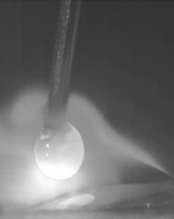
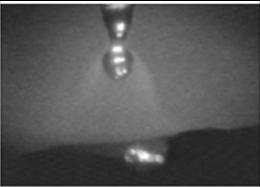
Only recently high speed video recording became industrially affordable and opened the door to welding process modeling. With such investigation means, it is possible now to characterize metal transfer precisely.
Figure 9: High speed video recording: Visualized arc modes.
The above shown photos and sequences are obtained with a high speed video camera, recording then arc phenomena at 6- 8 000 images per second. The classification obtained is as shown, the repelled spray area being situated before reaching the streaming spray.
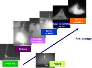
Natural short circuiting is used in all position welding, for root runs, or thin metal welding, the pulsed mode – a forced metal transfer- for quality welds in all position,
Figure 10: Short arc mode.

Figure 11: Pulsed mode.
avoiding the transition area, producing spattering, irregular weldments and high emissions. This transition area is reaching from globular to repelled spray.
Figure 12: Globular mode.

Figure 13: Globular free flight.

Figure 14: Repelled spray.

Figure 15: Axial streaming.

Axial streaming spray is the productive mode, with high deposition rates, low spattering, good wetting, especially in fillet welds, avoiding so crack opening areas, increasing fatigue resistance.
How do the different CO2 containing argon mixtures behave in this new environment?
A specific investigation about arc modes was carried out recently in the Air Liquide research center CTAS for welding and cutting applications. Purpose was to define a clear and coherent answer to customer drivers regarding the choice of a binary argon CO2 mixture, optimized for the process requirements currently requested. Different welding drivers WD may request different CO2 contents.
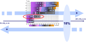
Figure 16: Welding drivers WD versus CO2 content in argon.

Mapping of metal transfer versus %CO2 and current
Each shielding composition was tested in a broad range of amperage/wire feeding rate, adapting the voltage to the CO2 content. For each welding voltage, amperage was recorded as well as the high speed video for arc visualization and analysis.
Figure 17: Mapping method of various CO2 contents, data recording & analysis + high speed video analysis.

The result is the mapping of the different arc modes and range of those for each composition.
A first finding is that a low oxidizing mixture, M20 as ISO 14175, and ranging from 8 to 15% CO2 is reaching a streaming spray mode far below 400A.
The 8% CO2 shows the spray threshold at 250A, giving the possibility to weld at high productivity with standard generators and gas cooled torches.
The globular range is reduced for such shielding gases which switch directly from free flight globular to streaming spray.
When reaching the medium oxidizing content of 15% a brutal change in the arc behavior occurs.
The globular mode- with different sub-properties- jumps to a broad spectrum of amperage. When the low oxidizing shielding gases show a spray threshold below 300A, the M21 oxidizing shielding gases reach a threshold of at least 400A.
Streaming spray will need in that case water cooled guns, and generators delivering at least 400A at 100% duty cycle.
The streaming spray for an 18% CO2 mixture is limited to a range of 400 to 440 A before getting into the swinging mode, loosing here part of the penetration potential.
Above 18% CO2 content, the standard mixtures 20 and 25% CO2 had been qualified. These mixtures are still considered as medium oxidizing (M21), but show a higher oxidation rate on the surface compared to an 18% CO2 mix. The streaming flow area is disappearing; the repelled spray switches directly into the swinging spray mode. Consequence is either continuous spattering or lack of penetration control.
Conclusion
Type of shielding atmosphere
Three types of shielding atmospheres can be considered as far as binary mixtures of CO2 and argon are concerned:
– Mixtures with low spray thresholds lower than 300A, useful for productive and quality welds. These mixtures show CO2 content below 15%. Pulsing is easy.
– Mixtures with CO2 contents between 15 and 18%, with pulsed capabilities, and versatile for flux cored and solid wire welding.
– Mixtures with major drawbacks in spattering and oxidation: above 18% CO2.
To show the consequence of the findings we’ll take in account the above requests for overall welding specifications, as welding costs, after weld cleaning due to oxides and spattering among others.
A good compromise is an 18% CO2 composition, which is the upper limit for streaming spray appearance, availability of generators, pulsed or not, and capability to weld flux cored and solid wires, rather tolerant to gap tolerances and surface contaminations.
Figure 18: 18% CO2 with still a streaming spray area.

It is the mixture closest to the main advantages of pure CO2 without its inconvenient.
The 8% CO2 mixture qualifies with the lowest oxidation rate, extremely stable arc properties, extra low spattering and highly productive, as the spray threshold is at 250A, reachable with any arc generator and gas cooled torches.
Such a composition allows easily welding at high speed in automatic mode with solid or metal cored wires.
This mixture qualifies with a broad process window opening and is today the reference for MAG carbon steel welding.
Figure 19: 8% CO2 with the lowest spray appearance amperage.
Here is shown the radar chart of performances when testing both of these reference mixtures.
Figure 20: Radar chart: weld acceptance criteria.
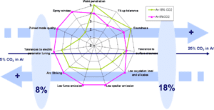
Each criterion has been measured under similar/identical conditions.It shows the advantages of each shielding in specific conditions. 18% CO2 is applying for heavier thicknesses with good penetration and fit up tolerance control, when the 8% mix allows the high productivity and speed. Also the arc striking properties, whatever the habit of the operator appears as best with the M20 mixture. This is important in particular for robotic or automatic welding, where downtimes due to arc striking issues have to be minimized.


