Kush P. Mehta, Department of Mechanical Engineering, School of Technology, Pandit Deendayal Petroleum University, Raisan, Gandhinagar-382007, Gujarat, India.
Abstract
In the present investigation, dissimilar materials electrolytic tough pitch pure copper to aluminum (6061-T651) welded with the favourable process parameters by friction stir welding (FSW).Tool pin profile and shoulder to pin diameter ratio parameters considered as tool design parameters. Rotational speed, welding speed, tool pin offset and tool tilt angle considered as process parameters. Four set of experiments were carried out to analyse tool design and process parameters of dissimilar copper (Cu) – aluminum (Al) FSW. Visual observation, macro structure, microstructural characterization and analysis of mechanical properties evolution used to identify favourable parameters after each set of experiment. The results revealed that cylindrical tool pin profile gives sound dissimilar Cu-Al friction stir welding. FSW process parameters of rotational speed 1500 rpm, welding speed 40 mm/min, tool pin offset 2 mm, tool tilt angle 2˚ with plunge load range 600-850 kgf enhance mechanical strength of 133 MPa and macro hardness of 181 VH (in the nugget zone) without any defect.
Keywords: Dissimilar materials, Friction Stir Welding, Process parameters, Weld properties
- Introduction
Dissimilar welding of copper (Cu) and aluminum (Al) is a challenge to perform as both of these materials are having differences in melting temperature, chemical compositions and physical properties. Despite of this, dissimilar Cu-Al joining is applied widely in many industries in order to take technical and economical advantages. Different industries such as electrical, nuclear, aerospace, chemical, solar and electronic use dissimilar Cu-Al joints for different applications. Friction stir welding (FSW) successively applied to join Cu-Al together since last few years. FSW is a solid state welding invented in 1991 by W. M. Thomas at the welding institute (TWI) to join Al alloys [1]. As the name implies, friction as well as stirring is responsible for making weld in solid state by non-consumable rotating tool, which has specially designed shoulder and pin. Friction between tool shoulder and work piece soften (i.e. plastically deformed) the area under tool shoulder and stirring of tool pin helps to move the soften material from front to rear [1].Joining of Cu and Al materials together is also difficult by FSW technology [2] but feasible [3].Microstructure of dissimilar Cu-Al FSW shows that it has vortex like and swirl flow under the area of tool [4]. Mixing of Cu and Al together is difficult due to differences in plastic deformation temperatures and vortex like flow between Cu-Al [2-4]. Generation of hard and brittle intermetallic compounds (IMCs) like Al4Cu9, AlCu, Al2Cu cannot be avoided for dissimilar Cu-Al FSW. More the IMCs generate more defects, which leads it to produce low strength joint [2 – 15].Therefore, it is necessary to reduce volume of IMCs for getting defect free-sound dissimilar Cu-Al FSW joint. A thin-continuous and uniform layer of intermetallic compounds improve the strength of dissimilar Cu-Al FSW joint [6, 8, 12, 16 – 17].Uniformity and continuous layer of IMCs of dissimilar Cu-Al joint depends on the process parameters optimization in friction stir welding [9, 16]. Variation in IMCs layer also varies metallurgical and mechanical properties of Cu-Al FSW joint. Researchers observed that tool design, tool pin offset, rotational speed, welding speed, location of Cu and Al in fixture (like Cu requires to be fixed at advancing side and Al requires to be fixed at retreating side for dissimilar Cu-Al FSW) are major process parameters which affects the IMCs and quality of dissimilar Cu-Al FSW joint. Akinlabi et al [18] found that varying shoulder diameter affects heat input conditions which also varies IMCs and mechanical properties of Cu-Al FSW. Optimum shoulder diameter 18mm produces highest strength (208 MPa) with appropriate material flow in stir zone out of three diameters 15 mm, 18 mm and 25 mm for dissimilar AA5754 to C11000 FSW joint [18]. Abdollah [5] observed that increase in rotational speed or decrease in welding speed increase the amount of IMCs and reduce its strength, whereas extremely low rotational speed results in imperfect joints. Galvao et al [9] observed that ratio of rotational speed to welding speed directly affects the heat input, IMCs and mechanical strength of dissimilar Cu-Al material. Optimum ratio of rotational speed to welding speed produce efficient defect free joint with higher strength. Esmaeilli et al [10]observed that change in rotational speed affects IMCs and mechanical behaviour of dissimilar brass-AA1050 joint. Xue et al [16] studied different parameters like fixed location, pin offset, rotational speed, welding speed on mechanical properties and microstructure of dissimilar Cu-Al FSW. Larger tool pin offset toward Al side helps to allow more stirring action at Al side and only small Cu particles scratched from Cu work piece, which makes defect free joint by easy mixing of Cu into Al matrix [8, 16]. It is reported that harder material copper require to fixed at advancing side in the fixture while performing dissimilar Cu-Al FSW so that, it can be easily transported and mixed with aluminum matrix and reduces defects in nugget [16, 19].
It is well documented that, there is a need to optimize process parameters to achieve highest strength with uniform IMC layer. Present investigation is carried out to detailed analysis for different process parameters like tool pin profile, tool pin offset, rotational speed, welding speed, tool tilt angle and axial plunge load for dissimilar (electrolytic tough pitch copper to AA6061-T651) materials. This study also includes optimization of all these parameters through experimental approach.
- Experimental Procedure
Aluminum 6061-T651 and electrolytic tough pitch copper (~99.9 purity) materials of 6.3 mm thickness were used to butt type join by friction stir technology. Chemical compositions of base materials are shown in Table:1. Tool steel of M2 grade (heat treated and 62HRC hardened) material was used in present investigation. Chemical composition of tool is shown in Table: 2.Experiments were carried out by keeping Cu at advancing side and Al at retreating side as shown in Fig: 1. Load cells were located below the fixture which reports the variation of axial plunge load throughout the dissimilar FSW.
Table: 1. Chemical composition of base materials
| Materials | Si | Fe | Cu | Mn | Mg | Cr | Zn | Ti | Impurities | Al | |
| Al 6061-T651 | 0.56 | 0.30 | 0.17 | 0.12 | 1.03 | 0.11 | 0.08 | 0.03 | 0.04 | Balance | – |
| Electrolytic copper | – | – | >99.9 | – | – | – | – | – | Balance | – | 97.15% Conductivity |
Table: 2. Chemical composition of tool
| Element | C | Cr | V | W | Mo | Co | Cb |
| Percentage (%) | 0.80 | 4.00 | 2.00 | 6.00 | 5.00 | _ | _ |
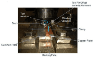
Fig: 1 Position of workpiece materials in fixture.
Experimental work is divided into four set of experiments. Tool design, tool pin offset, welding speed, rotational speed, tilt angle and axial plunge load are studied and optimized during experimental work. First set of experiment was carried out to study tool pin offset and tool design with taper pin profile. First set of experiment studies three experiments by varying tool pin offset 1 mm, 2 mm and 3 mm wherein keeping other parameters constant like tool dimension, rotational speed, welding speed and tilt angle as tool: 1 (as shown in Fig: 2), 1500 rpm, 30 mm/min and 0˚ respectively as shown in Table: 3.These three test coupons were checked visually and then subjected to macrostructure testing. For macro structure testing polishing of joint was done on grit paper 120 and 320 one by one. Based on its testing, changes in parameters were carried out and best result was taken as constant parameters for next set of experiment.
Table: 3 Process parameters for first set of experiment.
| Set of experiments | Rotational speed (rpm) | Welding Speed(mm/min) | Tilt angle (°) | Tool Pin Offset (mm) |
| 1 | 1500 | 30 | 0 | 1 |
| 2 | ||||
| 3 |
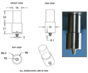
Fig: 2 Tool design 1.
Second set of experiment was carried out to study four different welding speeds 40 mm/min, 55 mm/min, 70 mm/min and 95 mm/min (Table: 4).Based on results of the first set of experiment, tool design was changed and new tool:2 is having cylindrical tool pin profile with increased dimensions as shown in Fig: 3. Tilt angle was also increased to 2˚ for second set of experiment. In addition to this, rotational speed kept 1500 rpm and tool pin offset was taken 2 mm for second set of experiment based on the results of first set of experiment. Visual checking and macrostructure test was taken after welding same as first set of experiment for conforming quality of welding. Based on it, the best result was taken as constant parameters for next set of experiment.
Table: 4 Second set of experiments.
| Set of experiments | Rotational speed (rpm) | Welding Speeds (mm/min) | Tilt angle (°) | Tool Pin Offset (mm) |
| 1 | 1500 | 40 | 0 | 1 |
| 55 | ||||
| 70 | ||||
| 95 |
Third set of experiment was carried out to study different rotational speeds 1100 rpm, 1300 rpm and1500 rpm (Table: 5).Based on the results of second set of experiment, 40 mm/min welding speed is taken for third set of experiment and other parameters kept constant such as rotational speed, tool pin offset and tilt angle kept 1500 rpm, 2 mm and 2˚ respectively. Specimens were checked visually and then tested by macrostructure analysis as well as mechanical and metallurgical analysis (like tensile testing, hardness testingand microstructure analysis) was carried out. Tensile specimens were prepared on miniature of lathe machine as per standard ASTM E8.Vickers macro hardness was measured within the indentation of every 2 mm along the transverse cross section of specimen with 10 kg load value as per standard ASTM, A370-07.Based on it, the best result was taken as constant parameters for next set of experiment.
Table: 5 Third set of experiment.
| Set of experiments | Rotational Speeds (rpm) | Welding speed (mm/min) | Tilt angle (°) | Tool Pin Offset (mm) |
| 1 | 1500 | 40 | 0 | 1 |
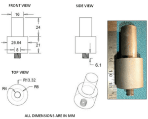
Fig: 3 Tool design 2.
Fourth set of experiments was carried out to study different tool tilt angles 0˚, 1˚, 2˚, 3˚and 4˚. Based on the results of third set of experiment, process parameters for fourth set of experiment are rotational speed 1300 rpm, welding speed 40 mm/min andtool pin offset 2 mm (Table: 6).Specimens were checked visually and then tested by macrostructure analysis as well as mechanical and metallurgical analysis same as analysed in third set of experiment.
Table: 6 Fourth set of experiment.
| Set of experiments | Rotational speed (rpm) | Welding speed (mm/min) | Tilt pin offset (mm) | Tilt angle (˚) |
| 1 | 1300 | 40 | 0 | 0 |
| 1 | ||||
| 2 | ||||
| 3 | ||||
| 4 |
- Results and Discussion
- First set of experiment
Visual examination was carried out from front side as well as rear side of tested coupons of first set of experiment as shown in Fig: 4.Average axial plunge load value for first set of experiment shown in Fig: 5.It shows that as the tool pin offset increases the average plunge load value decreases because the tool is more at softer material side i.e. aluminum side requires less force to stir the pin into it. Surface morphologies of all the samples were having minor hair cracks on it which is because of lack of heat input and lower value of plunge load. Macro results for first set of experiment shown in Fig: 6 which show that all the joints were having defects in their bottom of the nugget zones. Sample A and B big pores were observed whereas sample C there was not a joint at all from bottom side. Taper tool pin profile allows non uniform scratching of copper particles from top to bottom. Top side the copper particles scratched more and at bottom of pin copper particles scratched less. Because of non-uniform scratching mixing of copper particles into aluminum matrix is also non-uniform. So, the joints were not proper from the bottom side of nugget. Sample B (i.e. 2 mm tool pin offset) was found better than sample A and C. Pin offset was only 1 mm for sample A which means that tool pin remains more touched (2 mm) with copper base material. This allows more amounts of copper particles scratching which hard to mix with aluminum matrix because of its low flow ability and high conductivity. This led to the poor surface bonding and the formation of many big voids. On the other hand, for sample C the tool pin is almost at Al side as the pin offset is 3 mm. It was observed that joint is not proper at all from bottom side because the tool pin offset 3 mm was too large to weld 6.3 mm thick dissimilar Al-Cu FSW joint. For 3 mm offset, sufficient mixing of material cannot occurs because of very large pin offset as whole pin displaced at aluminum side. So, it is observed that pin offset 2 mm is more appropriate compares to other two offsets (i.e. 1 mm and 3 mm). It indicates that sufficient copper particles are scratched at 2 mm offset which allows proper mixing with aluminum matrix. The large copper particles mix with aluminum matrix and forms non-uniform intermetallic compound layer causes defects. This could be also the reason for more defects at nugget. First set of experiment suggest that taper tool pin profile is not suitable for dissimilar Cu-Al joint. More heat input and plunge force recommended for getting sound dissimilar weld.

Fig: 4 Welded coupons of first set of experiment; rotational speed 2000 rpm, welding speed 30 mm/min, tilt angle 0˚ and tool pin offsets (A: 1 mm, B: 2 mm and C: 3 mm).
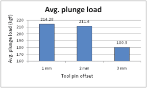
Fig: 5 Average axial plunge load value for first set of experiment.

Fig: 6 Macro results of first set of experiment; rotational speed 2000 rpm, welding speed 30 mm/min, tilt angle 0˚ and tool pin offsets (A: 1 mm, B: 2 mm and C: 3 mm).
3.2 Second set of experiment
Recommendations from first set of experiment have been applied before second set of experiment. Toll pin profile changed from taper to cylindrical for achieving uniform penetration in nugget zone. In addition to this tool pin size and shoulder size also increases as shown in Fig: 3 to increase plunge load value. Tilt angle increased from 0˚ to 2˚ and travel speed also increased from 30 mm/min to 40 mm/min to increase the value of axial plunge load. Visual examination was carried out from front side as well as rear side of tested coupons of second set of experiment as shown in Fig: 7. Average axial plunge load value for second set of experiment shown in Fig: 8.
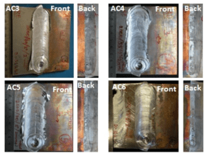
Fig: 7 Welded coupons of second set of experiment; rotational speed 2000 rpm, tool pin offset 2 mm, tilt angle 2˚ and welding speeds (AC3: 40 mm/min, AC4: 55 mm/min, AC5: 70 mm/min and AC6: 95 mm/min).
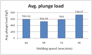
Fig: 8 Average axial plunge load value for second set of experiment.
The heat input is high at lower welding speed which makes base material softer and results in less value of axial plunge load compare to welding speed 95 mm/min. The heat input is low at high welding speed which increases the value of axial plunge load as it requires more force for stirring. Results shows improved surface morphologies with coupons of second set of experiment. Value of axial plunge load also increases (in the range of 520 to 730 kgf) as tilt angle, welding speed as well as shoulder diameter increases. Maximum plunge load 734.87 kgf at welding speed 95 mm/min shows that as increasing value of the welding speed the tool requires more force for stirring hence plunge load value increases. Macro structure results of second set of experiment shown in Fig: 9 in which defects of first set of experiment eliminated successfully and increased penetration level as shown in sample AC3. Uniform penetration achieved with cylindrical tool pin profile in which uniform scratching of copper particles from top to bottom in nugget allows proper bonding of Cu particles with aluminum matrix and form defect free joint.
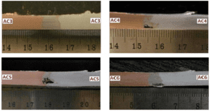
Fig: 9 Macro results of second set of experiment, rotational speed 2000 rpm, tool pin offset 2 mm, tool tilt angle 2˚ and welding speeds (AC3: 40 mm/min, AC4: 55 mm/min, AC5: 70 mm/min and AC6: 95 mm/min).
Defect free joint reported only with welding speed 40 mm/min whereas for other welding speeds 55, 70 and 95 mm/min defects were observed. Welding speed 40 mm/min allows more time to soften the aluminum material as the tool is more at aluminum side. Copper particles scratched from copper workpiece side flows easily as aluminum get softer which lead it to improve metallurgical bonding and mixing of both materials and make defect free joint. At higher welding speeds i.e. 55, 70 and 95 mm/min the defects were more because of lower heat input. Proper mixing of Cu particles into Al matrix would not achieved because of low heat input. From second set of experiment parameters of sample AC3 i.e. rotational speed 2000 rpm, welding speed 40 mm/min, tool tilt angle 2˚ and tool pin offset 2 mm recommended for further investigation on effect of rotational speed and tool tilt angle.
3.3 Third set of experiment
Third set of experiment carried out by keeping constant variables like tool design having cylindrical tool pin profile, welding speed 40 mm/min, tilt angle 2˚, tool pin offset 2 mm and rotational speed varied 1500, 1300 and 1100 rpm based on the results of second set of experiments. Visual examination was carried out from front side as well as from rear side of tested coupons of third set of experiment as shown in Fig: 10.Average axial plunge load value for third set of experiment shown in Fig: 11.At rotational speed 1100 rpm, the spindle stopped after plunging and before feed applied because the load or torque taking capacity of spindle found less enough to rotate the tool. Rotational speed 1100 rpm does not results in successful welding because the tool was not able to rotate with 1100 rpm. Variation of plunge load with different rotational speed is because of variation in heat input. As the rotational speed decreases the heat input also decreases and requires more force to stir at lower heat input. This is the reason for getting higher value of plunge load at 1300 rpm with compares to 1500 rpm. Macro structure results of third set of experiment shown in Fig: 12.It shows that as rotational speed changes from higher to lower size of stir zone also changes from higher to lower. Larger nugget zone is reported with rotational speed 1500 rpm and narrower reported with rotational speed 1300 rpm. Higher rotational speed generates stronger stirring action which enlarges nugget zone whereas lower rotational speed results in narrower nugget zone because of weak stirring action. In addition to this, no defects were reported in macro structure result of third set of experiment.
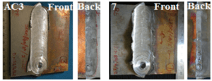
Fig: 10 Welded coupons of second set of experiment; tool pin offset 2 mm, tilt angle 2˚ and welding speed 40 mm/min, rotational speed (AC3: 2000 rpm and 7: 1700 rpm).
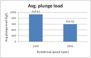
Fig: 11 Average axial plunge load value for third set of experiment.

Fig: 12 Macro results of third set of experiment; welding speed 40 mm/min, tilt angle 2˚, tool pin offset 2 mm and rotational speeds (AC3: 2000 rpm and 7: 1700 rpm).
Microstructure results for third set of experiment shown in Fig: 13 and Fig: 14.Four distinct microstructure zones were reported in aluminum-copper friction stir welding like Stir zone, Thermo mechanically affected zone (at Al-Al interface and at Al-Cu interface) and base material. The microstructure of copper and aluminum has an obvious boundary and the metal in stir zone shows obvious plastic combination between copper particles and aluminum matrix. Different copper particles distributed randomly in aluminum matrix such a way that it looks like islands in different sizes. Differences in grain structure of stir zone or weld zone for different rotational speed is because of differences in stirring action as well as differences in heat input. For higher rotational speed stirring action is stronger and makes weld zone grains are finer whereas for lower rotational speed stirring action is weaker and weld zone grains are coarser. This is the reason that at rotational speed 1500 rpm weld zone’s grains are finer than the rotational speed 1300 rpm. In addition to this, higher rotational speed 1500 rpm results in high heat input generates more and more intermetallic compounds at weld zone. For lower rotational speed 1300 rpm generation of intermetallic compounds is less.
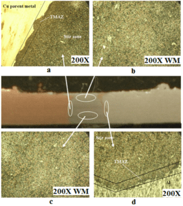
Fig: 13 Microstructure results for welding speed 40 mm/min, tilt angle 2˚, tool pin offset 2 mm and rotational speed 1700 rpm; (a: at Al-Cu interface, b: at weld metal-top, c: at Al-Al interface, d: at weld metal-bottom).
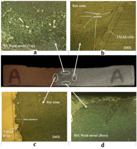
Fig: 14 Microstructure results for welding speed 40 mm/min, tilt angle 2˚, tool pin offset 2 mm and rotational speed 2000 rpm (a: at Al-Cu interface, b: at weld metal-top, c: at Al-Al interface, d: at weld metal-bottom).
Tensile strength and % elongation results for third set of experiment shown in Fig: 15 and Fig: 16 respectively. Increased tensile value 133 MPa reported with rotational speed 1500 RPM compare to tensile value 124 MPa at rotational speed 1300 RPM.As it is already discussed that softening of aluminum should be proper as it acts as matrix and scratched copper particles mixed with that matrix. Larger stir zone also allows copper particles to flow free in aluminum matrix. At higher rotational speed 1500 rpm nugget zone is larger as well as proper softening of aluminum achieved which is the reason for achieving high tensile strength value. Improper mixing between copper particles and aluminum matrix forms large brittle and hard intermetallic compounds in nugget zone as rotational speed low (1300 rpm) compares to1500 rpm. Large brittle and hard IMCs cause defects in nugget and reduces the tensile strength up to 124 MPa. Higher value of axial plunge load would also results in lower value of tensile strength. Fracture to elongation reported 4.4 % which is lower at rotational speed 1300 rpm whereas 11.5 % reported at rotational speed 1500 rpm. Lower elongation percentage is because of formation of large brittle non-uniform IMCs in nugget. Fracture location of tensile specimens for third set of experiment shown in Fig: 17. All the specimens were broken from thermo mechanically affected zone (TMAZ). Only one specimen was broken from TMAZ of aluminum-aluminum interface and others were broken from TMAZ of aluminum-copper interface. It shows that aluminum-copper interface is weaker microstructure zone out of all four microstructures. Most weak zone is TMAZ of aluminum-copper interface because of brittle layer of IMCs generated at interfaces between aluminum and copper.
Hardness variation for third set of experiment shown in Fig: 18. Hardness value observed high at the nugget area in both the samples because of presence of intermetallic compounds. On the other hand, the macro-hardness value at the nugget is increases as the rotation speed increases from 1300 rpm to 1500 rpm. At rotation speed 1500 rpm, more heat is generated compare to 1300 rpm which also results in more formation of intermetallic compounds. It is obvious that the presence of more IMCs at the nugget gives high hardness value.
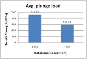
Fig: 15 Tensile strength results for third set of experiment.
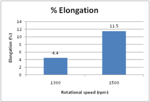
Fig: 16 % elongation results for third set of experiment.
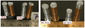
Fig: 17 Fracture locations of tensile specimens for third set of experiment.
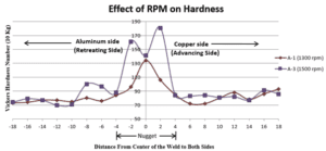
Fig: 18 Macro-hardness results for third set of experiment.
3.4 Fourth set of experiment
Fourth set of experiment carried out under different tool tilt angles 0˚, 1˚, 2˚, 3˚ and 4˚ while other parameters kept constant as rotational speed 1300 rpm, welding speed 40 mm/min and tool pin offset 2 mm based on results of third set of experiments. Visual examination was carried out from front side as well as from rear side of tested coupons of fourth set of experiment as shown in Fig: 19. Surface morphologies of all the coupons shows that as tool tilt angle increases the flash out effect of materials decreases. As tool tilt angle varies, the vertical and horizontal flow of material in stir zone also varies. Average axial plunge load value for fourth set of experiment shown in Fig: 20 in which increase in tilt angles also increases the plunge load value. Increases in forge load pushes material inside towards stir area and reduces flash out effect.
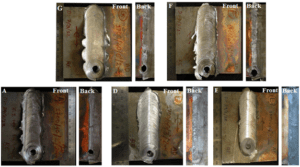
Fig: 19 Welded coupons of fourth set of experiment; rotational speed 1700 rpm, tool pin offset 2 mm, welding speed 40 mm/min and tool tilt angles (G: 0˚, F: 1˚, A: 2˚, D: 3˚ and E:4˚).
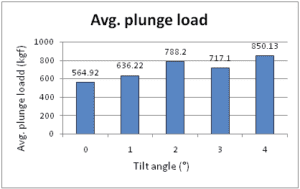
Fig: 20 Average axial plunge load value for fourth set of experiment.
Macro results for fourth set of experiment shown in Fig: 21, in which samples of 0˚ and 1˚ tilt angles having minor defects in nugget zone whereas samples of 2˚, 3˚ and 4˚were defect free. It shows that as tilt angle increases the defects decreases because tilt angle 2˚ or more than it provide enough forging force as well as uniform material flow from top to bottom at nugget whereas low tilt angle provides low forging force as well as non-uniform vertical material flow from top to bottom nugget. Additionally, triangle shape of the stir zone is also varying with variation in tool tilt angle. Base of triangle size increases as well as top cone size decreases with increases the value of tilt angle. The reason for this is different vertical and horizontal material flow in weld nugget with variation of tilt angles. Increasing the tilt angle, improves the flow characteristics of the weld material and hence, tool movement forges the weld material better to fill the defects and consequently increases the weld strength as shown in Fig: 22. Fracture to elongation results for fourth set of experiment shown in Fig: 23. Higher tensile strength 116 MPa reported with 4˚ tilt angle and lower tensile 100 MPa value reported with 1˚ tilt angle. Fracture to elongation reported maximum 6 % for tilt angle 3˚ and 4 % reported for rest of others. Lower value of overall fracture to elongation again proves the presence of intermetallic compounds in the nugget zone. Fracture location for tensile test for fourth set of experiment shown in Fig: 24.Results of fracture locations were consistent with third set of experiment broken almost from TMAZ of copper-aluminum interface. It also proves the weakest location in copper-aluminum dissimilar FSW joint is copper-aluminum interface. Large amount of IMCs present at copper-aluminum interface makes it weaker zone.
As it discussed earlier that material flow varies with change in tilt angle which also prove that intermetallic compounds also varies with different tilt angles. Higher amount of IMCs produce higher hardness at nugget. Hardness variation for fourth set of experiment shown in Fig: 25.Increase in tilt angles also increases the value of hardness at nugget area. Maximum macro-hardness 186 VH is observed at nugget with tilt angle 4°. Minimum macro-hardness 58 VH is observed at nugget with tilt angle 0°.It proves that increase in tilt angle also increases the IMCs at nugget zone. Additionally, all the specimens were hardened from nugget area as same as reported with third set of experiment which is because of presence of hard brittle IMCs at nugget.
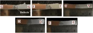
Fig: 21 Macro results of fourth set of experiment;rotational speed 1700 rpm, tool pin offset 2 mm, welding speed 40 mm/min and tool tilt angles (G: 0˚, F: 1˚, A: 2˚, D: 3˚ and E:4˚).
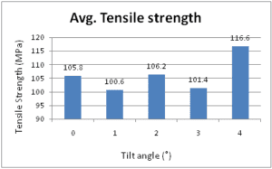
Fig: 22 Tensile strength results for fourth set of experiment.
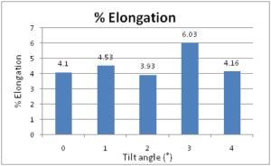
Fig: 23 % elongation results for fourth set of experiment.
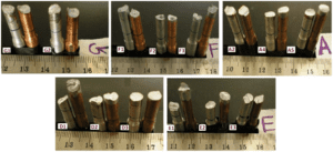
Fig: 24 Fracture locations of tensile specimens for fourth set of experiment.
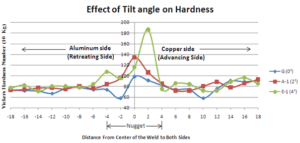
Fig: 25 Macro-hardness results for fourth set of experiment.
- Conclusions
The influence of tool pin profile and process parameters for dissimilar material (Copper to 6061-T651 aluminum) friction stir welding was analysed successfully. The following conclusions can be made.
- AA6061-T651 and electrolytic touch pitch copper were successfully welded by friction stir welding technology by cylindrical tool pin profile. On the other hand, taper tool pin profile was not suitable to produce defect free Cu-Al dissimilar FSW joints.
- Optimum process parameters based on maximum tensile strength (133 MPa) for dissimilar AA6061-T651 to electrolytic tough pitch copper friction stir welding as below. Rotational speed: 1500 rpm, Welding speed: 40 mm/min, Tool tilt angle: 2°-4°
Tool pin offset: 2 mm, Axial plunge load range: 650-850 kgf
- Stir zone or nugget area size varies with different rotational speeds. Higher rotational speed produce larger stir zone and lower rotational speed produce narrower stir zone.
- Weakest zone of dissimilar Cu-Al FSW joint is thermo mechanically affected zone (TMAZ) as tensile specimens almost fractured from TMAZ of copper-aluminum interface.
- Micro-structure stir zone consists of composite structure with variously sized particles dispersed in the aluminum matrix.
- Increase in rotational speed and tilt angle increases the value of macro-hardness.
- Flash out effect of dissimilar materials FSW reduced by increasing the tilt angle 2º to maximum 4°.
- Maximum macro-hardness 188 VHN and lower fracture to elongation at the nugget area proves intermetallic compounds at the nugget zone of dissimilar Cu-Al FSW joint.
References
[1] R. S. Mishra, Z. Y. Ma. Friction stir welding and processing. Material science and engineering: R:Rep 2005; 50:1–78.
[2] J. Ouyang, E. Yarrapareddy, R. Kovacevic. Microstructural evolution in the friction stir welded 6061aluminum alloy (T6-temper condition) to copper. Journal of materials processing technology 2006; 172:110-122.
[3] A. Elrefaey, M. Takahashi, K. Lkeuchi. Preliminary investigation of friction stir welding aluminum/copper lap joints. Welding in the world, Issue 3-4 2005; 49: 93-101.
[4] L. E. Murr, Ying Li, R. D. Flores, Elizabeth A. Trillo. Intercalation vortices and related microstructural features in the friction stir welding of dissimilar metals. Material Research Innovations 1998; 2: 150-163.
[5] A. Abdolla-Zadeh, T. Saeid, B. Sazgari. Microstructural and mechanical properties of friction stir welded aluminum/copper lap joints. Journal of alloy and compounds 2008; 460: 535-538.
[6] P. Xue, B.L. Xiao, D.R. Ni, Z.Y. Ma, 2010. Enhanced mechanical properties of friction stir welded dissimilar Al–Cu joint by intermetallic compounds. Materials Science and Engineering 2010; A 527: 5723–5727.
[7] T. Saeid, A. A. zadeh, B. Sazgari. Weldability and mechanical properties of dissimilar aluminum–copper lap joints made by friction stir welding. Journal of Alloys and Compounds 2010; 490: 652–655.
[8] C. Genevois, M. Girard, B. Huneau, X. Sauvage, and G. Racineux. Interfacial reaction during Friction Stir Welding of Al and Cu. Metallurgical and materials transactions 2011; 42A: 2290-2295.
[9] I. Galvao, C. Oliveira, A. Loureiro and D. M. Rodrigues. Formation and distribution of brittle structures in friction stir welding of aluminum and copper: influence of process parameters 2011; 16: 681-689.
[10] A. Esmaeilli, H. R. Zareie, M. Sharbati, M. K. Besharati, M. Shamanian. The role of rotational speed on intermetallic compounds formation and mechanical behaviour of friction stir welded brass/aluminum 1050 couple. Intermetallics 2011; 19: 1711-1719.
[11] J. Kandasamy, M. Manzoor Hussain, S. Rajesham. Hetrogeneous friction stir welding: Improved properties in dissimilar aluminum alloy joints through insertion of copper coupled with external heating. Materials and manufacturing processes 2012; 27: 1429-1436.
[12] M. N. Avettand-Fenoel, R. Taillard, G. Ji, D. Goran. Multiscale study of interfacial intermetallic compounds in a dissimilar Al 6082-T6/Cu friction stir weld. Metallurgical and materials transactions 2012; 43A; 4655-4666.
[13] R. Beygi, M. Kazeminezhad, A. H. Kokabi. Butt joining of Al-Cu bilayer sheet through friction stir welding. Transaction of nonferrous metals society of china 2012; 22: 2925-2929.
[14] M. Akbari, R. Abdi Behnagh. Dissimilar friction stir lap joining of 5083 aluminum alloy to CuZn34 brass. Metallurgical and materials transactions 2012; 43B: 1177-1186.
[15] C. W. Tan, Z. G. Jiang, L. Q. Li, Y. B. Chen, X. Y. Chen. Microstructureal evolution and mechanical properties of dissimilar Al-Cu joints produced by friction stir welding. Materials and design 2013; 51: 466-473.
[16] P. Xue, D. R. Ni, D. Wang, B. L. Xiao, Z. Y. Ma. Effect of friction stir welding parameters on the microstructure and mechanical properties of the dissimilar Al-Cu joints. Materials science and engineering 2011; A528: 4683-4689.
[17] S. Kahl, W. Osikowicz. Composite aluminum-copper sheet material by friction stir welding and cold rolling. Journal of materials engineering and performance 2013; 22: 2176-2184.
[18] E. T. Akinlambi. Effect of shoulder size on weld properties of dissimilar metal friction stir welds. Journal of materials engineering and performance 2012; 21:1514-1519.
[19] I. Galvao, D. Verdera, D. Gesto, A. Loureio, D. M. Rodrigues. Analysing the challenge of aluminum to copper FSW. 9th friction stir welding symposium 2012.


