
Hasan Shaikh, Scientist (Retd.),
Indira Gandhi Centre for Atomic Research,
Kalpakkam
The more often encountered phenomenon, which degrades the corrosion resistance of an austenitic stainless steel weld joint is the sensitisation of the heat affected zone (HAZ). Sensitisation of austenitic stainless steel occurs in the temperature range of 723 to 1123 K. During this high temperature exposure, depletion of Cr to less than 12% occurs in the region around the grain boundary, due to the precipitation of a continuous network of M23C6 carbides. Sensitisation makes the steel susceptible to intergranular attack. The probability of the HAZ being sensitised during welding would depend on the time it spends in the sensitisation temperature range. Fig. 1 illustrates the maximum time spent by four different regions of the HAZ in the sensitisation temperature range. The region, which experiences a peak temperature of 1123 K is sensitised maximum. Below 723 K, carbide precipitation is too sluggish to cause any concern. The residence time spent by the HAZ in this temperature range depends on the heat input, which in turn depends on the heating and cooling rates. Fig. 2 shows that for a butt weld configuration for thicker sections, increasing heat input increases the time spent by the HAZ in the sensitisation temperature range. Also, the use of higher interpass temperatures increases the probability of sensitisation of HAZ [1].
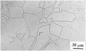
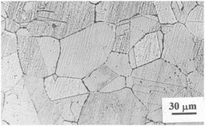
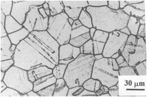
Fig. 3 schematically illustrates the microstructure of a sensitized austenitic stainless steel after etching in oxalic acid. Optical microscopy reveals any of the three structures viz. step, ditch and dual. Step structure corresponds to clean grain boundaries and, hence, an annealed structure. Ditch structure means continuous carbide depletion and corresponds to a probably sensitized structure. Dual structure would mean discontinuous carbide precipitation. Normally, step and dual structures are screened to be non-sensitised as per ASTM standards. However, this could be a mistake since dual structure could result in a fully ditched structure during low temperature service. Sensitization in austenitic stainless steels can takes place after long exposure at 300°C, if such steels were first exposed briefly in the sensitization range prior to low temperature exposure. This kind of thermal cycle is experienced in welded stainless steels used in Boiling Water Reactor (BWR) and termed as low temperature sensitization (LTS). Kain et al. [2] reported that type 304 stainless steel and its variants are more prone to LTS than the molybdenum containing type 316 stainless steels. Fig. 4 illustrates the relationship between M23C6 precipitation and IGC. It is seen that the curve indicating IGC is offset to the right of carbide precipitation curve. This indicates a time lag between onset of carbide precipitation and susceptibility to IGC. This is because though carbide precipitation would occur, the regions adjacent to the carbides at grain boundaries have to be sufficiently depleted of Cr (< 12%) for IGC to occur [3]. The kinetics of the chromium carbide precipitation, and, hence, the resultant sensitisation could be predicted from a time-temperature-sensitisation diagram (TTS) (Fig. 5) [4]. These curves represent sensitisation during isothermal heat treatments. However, sensitisation during welding can be predicted by a continuous cooling sensitisation (CCS) diagram (Fig. 6) [5].
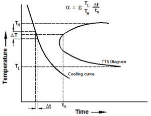
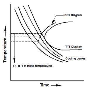
The CCS curves are constructed from the TTS diagrams by superimposing the cooling curves. Dayal and Gnanamoorthy have reported a method to predict the extent of sensitization during cooling/heating of the material [6]. The principle of this method is described in Fig. 7. The cooling curve is divided into a number small segments (DT) from the highest temperature (TH) to the lowest temperature (TL) of the relevant TTS diagram. The time of transit Dt is determined for each segment of the cooling curve and is divided by the sensitization time (ts) at the mean temperature T of this segment from the TTS diagram. The cumulative fraction (a) of the resident time in successive segments from TH to TL is calculated and is defined as
TH
a = S Dt/ts
TL
Sensitization takes place if a > or = 1. With this equation a critical cooling rate (R) to cause sensitization can be calculated and is given as per the equation
TH
R = DT S 1/ts
TL
The value of a is not dependent on magnitude of DT. For agiven cooling rate slower than the critical cooling rate, a temperature can be found at which a = 1. This gives one point on the CCS diagram. For different cooling curves, the loci of such points determine the continuous cooling sensitization diagram.
Susceptibility to IGC caused by sensitisation in austenitic stainless steel can be determined by systematically carrying out ASTM standardized tests. The ASTM tests for IGC are either chemical or electrochemical in nature and are applicable for austenitic stainless steel and some Ni-base alloys. ASTM Standard A 262 Practice A to F are the standards for chemical and metallographic tests to determine IGC in austenitic stainless steel [7].
Table 1 gives a comparative analysis of the various ASTM A 262 Practices to detect sensitization. These standard tests are commonly used as qualification/acceptance criteria during purchase/fabrication stage. However, non-inclusion of acceptance limits in these standards leaves the interpretation of results open to users. Besides not quantifying the degree of sensitisation (DOS), these chemical tests are also destructive and slow – a situation that is not welcome at plant site. The oxalic acid etch test (A262 Practice A) is normally used as a screening test. Only if a ditched microstructure is observed in oxalic etch test, the need for confirmatory tests (Practice B to F) is necessary. The most often used chemical technique isthe ASTM A262 Practice E test, which is popularly known as the Strauss test. The test recommends a bend test after exposure to Cu-CuSO4-H2SO4 test medium to qualify the material. However, the bend test does not give any quantitative value for the DOS. Electrical resistivity and tensile properties are changed considerably by the intergranular attack in the Strauss test medium. Hence the changes in these properties can be used to quantify the DOS after exposure to the Strauss test solution [8]. To overcome these limitations of chemical tests, an electrochemical technique, known as electrochemical potentiokinetic reactivation (EPR) technique, was developed by Cihal et al. [9], Novak et al. [10] and Clarke et al. [11]. This technique is a quantitative, non-destructive and rapid method, which is essentially suitable for field use. This technique was standardised by ASTM to quantify the DOS in AISI types 304 and 304L stainless steel [12]. The EPR technique has been successfully used to quantify the DOS in other stainless steel and Ni base alloys [13,14]. Table 2 gives the conditions for the EPR test. Two versions of the EPR technique are practiced today, viz. the single loop technique (Fig. 8) and the double loop technique (Fig. 9). Double loop technique has advantage over single loop technique in that it automatically compensates for changes in alloy composition, and in that the surface finish is not very critical, which makes it an automatic choice for on-field applications. Reactivation charge, ratio of reactivation to activation charge, peak reactivation current density, ratio of peak current densities on reactivation to activation are some of the parameters used to quantify degree of sensitisation. However, discrepancies exist between the DOS determined by chemical methods and the EPR method [14]. The threshold EPR charge value above which a stainless steel is susceptible to IGC in ASTM A262E is not a unique number, but depends on temperature at which the material was sensitised. This is because the ratio of the width to depth of the Cr-depleted regions affects the reactivation charge during the EPR test. EPR tests have an inherent disadvantage in that they are very sensitive to changes in Cr depletion anywhere in the alloy and cannot differentiate between matrix and grain boundary depletion.
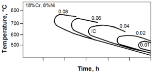
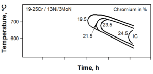
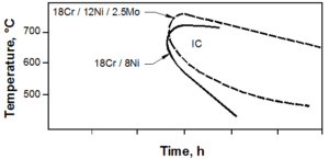
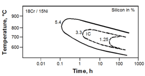
Sensitisation of austenitic stainless steel requires the precipitation of Cr-rich carbides along grain boundaries, which makes carbon and Cr the predominant compositional variables for sensitization. By reducing the carbon content in stainless steel, TTS curve is displaced towards longer times because carbon concentration in austenite becomes insufficient to form Cr-carbide readily (Fig. 10a) [15]. The limit of C content for which steel is not sensitive to IGC is closely connected with the presence of other alloying elements such as Cr, Mo, Ni, N, Mn, B, Si as well as Ti & Nb in stabilized steel. The detrimental effect of C on sensitization can be reduced by the addition of stabilizing elements like Ti and Nb. These elements form TiC and NbC, which results in reduction of Cr available for Cr-carbide precipitation. Cr has a pronounced effect on the passivation characteristics of stainless steel. With higher Cr contents, time to reach resistance limit of Cr depletion at the grain boundaries is shifted to longer times (Fig. 10b). Higher Cr contents facilitate the diffusion of Cr into depleted grain boundary area [15]. Ni is required in austenitic stainless steel to stabilize the austenite and must be increased with increasing Cr concentration. Increasing the bulk Ni content decreases the solubility and increases the diffusivity of C. This effect is much more pronounced when Ni content is greater than 20%. It is generally recommended that in 25/20 Cr-Ni steel, C content should be less than 0.02% to guarantee resistance to IGC. Mo reduces the solubility of C in austenite. Carbide precipitation is accelerated at higher temperatures whereas at lower temperatures it is slowed down (Fig. 10c) [15]. When Mo is present, it is also incorporated in M23C6. Therefore, in addition to Cr depletion, Mo depletion is also revealed. In Mo-containing Cr-Ni austenitic stainless steel, (Fe,Cr)23C6 is precipitated first at 1023 K to 1123 K. With prolonged aging, Mo is also incorporated as (Fe,Cr)21 Mo2C6 which is finally converted to c phase. With increasing Mo contents, M23C6 precipitation and IGC become increasingly influenced by the precipitation of intermetallic phases. The influence of Mn is of special importance because in fully austenitic welds, this element is added. Mn reduces the carbon activity and increases its solubility. Carbide precipitation is slowed down and hence it appears to inhibit carbide precipitation [16]. Boron retards the precipitation of Cr-carbide but depending upon the heat treatment it promotes IGC]. Si promotes IGC of high purity and commercial stainless steel. Steels containing Mo were found to be much more sensitive to Si additions. The increased susceptibility to IGC in highly oxidizing solution is due to the segregation of Si to grain boundaries [15]. Fig. 10d represents the influence of Si on the kinetics of sensitization. One of the alloying additions studied extensively in the recent years is nitrogen. Its effect is quite complex and is dependent on the presence of other alloying additions. N content up to 0.16 weight % is reported to improve sensitization resistance by retarding the precipitation and growth of Cr23C6 [17]. Parvathavarthini et al. have established that as the nitrogen content increases, time required for sensitization at the nose temperature increases from 0.5 hours (316 stainless steel) to as much as 80 hours (316 LN stainless steel) indicating the beneficial effect of N [18].
Based on numerous data in literature, the effect of chemical composition on sensitization behaviour of austenitic stainless steels has been described by an effective chromium content, Creff, by giving proper weightages to various elements as [19,20]
Creff = Cr + 1.45 Mo – 0.19 Ni – 100 C + 0.13 Mn – 0.22 Si – 0.51 Al – 0.2 Co + 0.01 Cu + 0.61 Ti + 0.34 V – 0.22 W + 9.2 N
Table 3 relates Creff to the critical cooling rates. It is seen that as increases, the critical cooling rate, above which sensitization will not occur, decreases [19,20].Cr-carbides precipitate at grain boundaries because they are high energy areas. As the grain size decreases, the grain boundary area available for Cr-carbide precipitation increases. This would cause the effective depletion of Cr per unit grain boundary area to reduce. Also, Cr has to diffuse smaller distances to heal the Cr-depleted regions to desensitize the material. Cold work is reported to increase the sensitization kinetics of austenitic SS at moderate cold works and decrease the kinetics at higher cold works. Parvathavarthini et al. [5] reported that TTS diagrams of cold worked materials are shifted to the left (shorter times) with increasing cold work, and below that of the as-received material. The nose temperature corresponding to maximum rate of sensitization is also shifted to lower temperature with increasing cold work. Desensitisation is faster at higher levels of cold work especially at high aging temperatures.
SUMMARY
The paper discusses the various aspects of sensitization of heat affected zone of austenitic stainless steels. Sensitisation makes the steel susceptible to intergranular attack. The probability of the HAZ being sensitised during welding would depend on the time it spends in the sensitisation temperature range. The kinetics sensitization during isothermal annealing could be predicted from a time-temperature-sensitisation diagram (TTS); while sensitisation during welding can be predicted by a continuous cooling sensitisation (CCS) diagram. Susceptibility to intergranular corrosion (IGC) caused by sensitisation in austenitic stainless steel can be determined by systematically carrying out ASTM standardized tests. The various chemical and electrochemical ASTM tests for IGC have been discussed. The effect of chemical composition on sensitisation and the minimum required critical cooling rates to prevent it have been discussed.
REFERENCES
- T. P. S. Gill, Proceedings of the Corrosion Management Course, The Indian Institute of Metals, Kalpakkam, October 1995, Paper No. L-6
- V. Kain, K. Chandra, K. N. Adhe and P. K. De, Journal of Nuclear Materials, 334(2004) 115
- C. J. Novak, Handbook of Stainless Steels, 1977
- S. K. Mannan, R. K. Dayal, M. Vijayalakshmi and N. Parvathavarthini, Journal of Nuclear Materials, 126 (1984) 1
- N. Parvathavarthini, R. K. Dayal, J. B. Gnanamoorthy and S. K. Seshadri, Journal of Nuclear Materials, 168 (1989) 83
- R. K. Dayal and J. B. Gnanamoorthy, Corrosion, 36 (1980) 104
- ASTM Standard A262-93a, ASTM Book of Standards, American Society for Testing of Metals, Philadelphia PA, (1993) 42
- P. Muraleedharan, Corrosion and Maintenance, (1984) 47
- V. Cihal, Corrosion Science, 20 (1980) 737
- P. Novak, R. Stefec and F. Franz, Corrosion, 31 (1975) 344
- W. L. Clarke, W. M. Romero and J. C. Danko, Report GEAP-21382, GEC, California,(1976)
- ASTM Standard G 108-94, ASTM Book of Standards, American Society for Testing of Metals, Philadelphia PA, (1994) 444
- W. L. Clarke, J. R. Kearns, J. Y. Park and D. van Rooyen, ASTM Research Report,
Subcommittee G01.08, 1989
- P. Muraleedharan, J. B. Gnanamoorthy and K. Prasad Rao, Corrosion, 45 (1989) 142
- E. Folkhard, Welding Metallurgy of Stainless Steels, Springer-Verla, Vienna (1988)
- C. L. Briant, R. A Mulford and E. E. Hall, Corrosion, 38 (1982) 468
- T. A. Mozhi, W. A. T. Clarke, K. Nishimoto, W. B. John and D. D. McDonald,
Corrosion, 41 (1985) 555
- N. Parvathavarthini, R. K. Dayal and J. B. Gnanamoorthy, Corrosion, 208 (1994) 251
- N. Parvathavarthini and R. K. Dayal, Journal of Nuclear Materials, 305 (2002) 209
- R. K. Dayal, N. Parvathavarthini and Baldev Raj, International Materials Reviews, 50
(2005) 129
Table 1: ASTM Evaluation Test for Detecting Sensitization
| ASTM Practice | Test Environment | Potential Range | Alloys | Phases Attacked | Evaluation Criteria |
A |
Oxalic Acid Etch | +1.76 V (SCE) | 304, 304L, 316, 316L, 317, 317L, 321, 347 | Carbides | YES |
| B | Fe2(SO4) – 50% H2SO4 | +0.6 V (SCE) | 321,347 | s in 321 & 347 | NO |
C |
HNO3 | +0.96 V (SCE) | 321,347 | Cr-depleted regions, carbides & Mo-bearing s | NO |
| D | HNO3 – HF | +0.3 to –0.1 V (SCE) | 316,317,317L | Cr-depleted region | NO |
| E | Cu–CuSO4/16% H2SO4 | +0.34 V (SCE) | 316,316L, 317,317L | Cr-depleted region | YES |
| F | Cu–CuSO4/50% H2SO4 | — | Low carbon and Mo-bearing SS | Cr-depleted regions | NO |
Table 2: EPR Test condition as used by Clarke et al.
| Electrolyte | 0.5M H2SO4 +0.01M KCNS |
| Temperature | 300C |
| Specime surface finish | 1 micron (diamond paste) |
| Reactivation Sweep Rate | 6 V/h |
| Passivation Potential / Time | +200 mv for 2 minutes |
| Deaeration | Nitrogen |
Table 3: Dependence of critical cooling rates on Creff
| % CW | 12.57 | 14.36 | 16.03 |
| 0 | 365 | 17 | 0.43 |
| 5 | 710 | 22 | 0.54 |
| 10 | 765 | 27 | 0.73 |
| 15 | 515 | 27 | 0.76 |
| 20 | 815 | 26 | 0.93 |
| 25 | 790 | 18 | 0.97 |
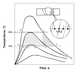
Fig. 1: A schematic diagram indicating the effect of thermal cycling in inducingsensitisation in HAZ
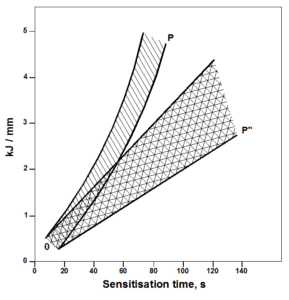
Fig. 2: Relationship between heat input and maximum time spent by HAZ for welds made with 373 K and room temperature interpass temperatures
(a)
(b)
(c)
Fig. 3: Microstructures showing (a) step structure, (b) dual structure and (c) ditch structure
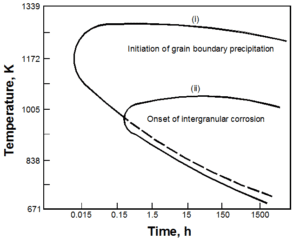
Fig. 4: Relationship between M23C6 precipitation and intergranular corrosion in type 304 stainless steel

Fig. 5: Time-temperature-sensitisation (TTS) diagram for types 316 (1-1), 316N (2-2) and 316LN (3-3) stainless steels
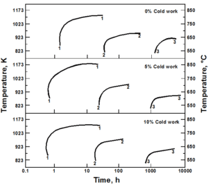
Fig. 6: Continuous cooling sensitization (CCS) diagram for types 316 (1-1), 316N (2-2) and 316LN (3-3) stainless steel
(a)
(b)
Fig. 7: Continuous cooling sensitization diagram obtained from TTS diagram (a) principle of the method, and (b) the procedure
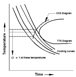
Fig. 8: Single loop technique of EPR test
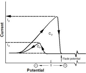
Fig. 9: Double loop technique of the EPR tests
(a)
(b)
Fig. 10: Influence of (a) carbon (b) Cr (c) Mo and (d) Si, on the sensitization kinetics
(c)
(d)
Fig. 10: Influence of (a) carbon (b) Cr (c) Mo and (d) Si, on the sensitization kinetics


