Swagat Dwibedi, Assistant Professor,
Veer Surendra,Sai University of Technology, Burla

Swarup Bag, Associate
Professor, Department of Mechanical Engineering,
Indian Institute of Technology Guwahati
With miniature of components, the demand for small scale products is ever increasing. Hence the downscaling of the conventional welding process is utilized to develop several microwelding processes. The concentrated and well controlled power density is the primary requirement for small scale welding process. Hence, apart from laser or electron beam, the development of arc welding find a place in small scale welding application. Production of low amperage current in continuous mode as well as well-regulated pulse mode makes it possible for micro plasma arc to apply in small scale welding process. The current below 15 A is used for micro plasma arc welding (µ-PAW)to join several metallic materials like low carbon steel, stainless steel, maraging steel, titanium alloy and even nickel based super alloy. The development of µ-PAW process for these materials can be considered as an alternative for laser welding in terms of equipment cost. However, the fixture and backing plate used for holding and manipulating the small components play an important role for successful development of small scale welding process.
Introduction
The plasma arc welding (PAW) is one of the variants of arc welding processes where the joining of the materials is mainly achieved through transferred arc. The non-transferred arc is mainly used for chemical vapour deposition, plasma spraying, waste treatment, and production of ultra-fine powders [1]. Three different modes of current are mainly used in PAW process: micro-plasma, melt-in mode, and keyhole plasma. The downscaling of PAW process where the current ranges from 0.1 to 15 A is mainly used for small scale welding process. Welding of thin sheets is significant in several engineering field where dimensional tolerances and residual distortion of the weld joint is major concern. One of the common welding methods of thin sheet is gas tungsten arc welding (GTAW). However, high input resulting in greater distortion is a major drawback of GTAW welding [2]. Plasma arc welding (PAW) is known to its greater energy concentration than GTAW process, deep penetration with greater arc stability and better control of the process [1]. PAW technique has lower equipment cost and adopts large tolerance between gaps and misalignment than highly focused laser beam or electron beam [1-2].
Therefore, PAW is good alternative and cost effective than laser or electron beam welding in industrial application. Recent development on constricted and regulated arc even at low current in micro plasma process makes it possible to apply in micro scale welding process which is more advantageous than GTAW process. However, the application of μ-PAW is not explored for a wide range of materials. The positioning of the electrode brings the difference between GTAW and PAW where the constriction of plasma arc is possible rather than the open type of arc for GTAW (~ approximately 3 times power density than GTAW). Also, the plasma arc can be separated from the shielding gas envelope. Hence the controlled and regulated arc in case of PAW is possible to generate which is considered as the advancement over GTAW process. The µ-PAW can create deep penetration and even run in keyhole mode. Since the electrode is protected, it offers longer life. It creates stable arc and may run in low amperage current (~ 0.05 A). It is observed that lots of research work has come up on the establishment of small scale welding process using laser system. However, very limited work has found in esteemed literature on small scale welding using μ – PAW process although it is one of the low cost systems, at least, as compared to laser welding process. Therefore, establishment of μ – PAW system for different materials has significance in current scenario of miniature components. The analysis on comparative mode between different materials is useful to establish the parameters for welding of dissimilar materials. The range of parameters (current, voltage, speed) or a combined of parameters (heat input per unit length) is important to know to develop successful weld joint for a specific material.
Recent Advancement
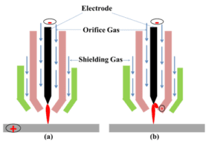
To initiate the arc in PAW, a low current pilot arc is obtained between the electrode and the constricting nozzle first, which ionizes the plasma gas flowing through the nozzle. The plasma gas flowing through the constriction reaches a very high temperature, and provides a low resistance path to initiate the plasma arc between the electrode and the workpiece; this is termed as a transferred arc. The transfer arc flows through the nozzle and extends its path to reach the base metal, forming a low resistance path of current between the tungsten electrode and the base metal. The plasma arc is with high temperature and velocity due to the restriction by the orifice, fusing and joining the metal pieces as desired. The plasma gas itself is not sufficient to protect the weld metal and therefore, a large volume of inert shielding gas is allowed to flow through an outer gas nozzle surrounding the inner nozzle. The shielding gases generally use inert type gases like argon, or helium and may be similar of plasma producing gas. The arc formed between the electrode and the constricting nozzle, is termed as non-transferred arc. In transferred arc, as the workpiece forms a part of the electrical circuit, high energy density, and high penetration is achieved as compared to non-transferred arc. Transferred arc finds application in the area of welding where as non-transferred arc is used mainly for thermal spraying and joining of non-conductive workpiece. Fig. 1 depicts difference between transferred and non-transferred arc in PAW [3].

Fig. 1 : Concept of (a) transferred and (b) non-transferred arc in PAW [3].
Many variants of PAW processes have been developed, i.e. pulsed plasma arc welding (P-PAW), variable polarity plasma arc welding (VPPAW), double sided arc welding, ternary gas plasma arc welding, laser-assisted plasma arc welding, PAW-MIG hybrid welding process, soft plasma arc welding, plasma spot welding process, manual pulse keyhole PAW and increased power density PAW [4]. Table 1 shows the comparison between different variants of PAW.
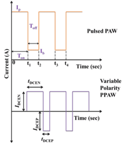
One of the variant of plasma arc welding is its pulse mode, in which there are two current levels, peak current (Ip) and base current (Ib). Peak current is the maximum value of pulse current during pulse-on time and it must be sufficient enough to melt the material and base current is the minimum value of the pulsed current during pulse-off time and it must be sufficient enough to maintain the arc. The low current or base current level is set at a value just sufficient to maintain an arc without causing significant plate melting. The ideal pulse current level is determined by the thermal properties of the material and should be set at a level which will ensure that the weld pool can propagate at a rate that is fast enough to ensure the maximum thermal efficiency. Another variant of PAW is variable polarity plasma arc welding (VPPAW). VPPAW finds application in welding of aluminium alloys, because surface oxide film formed, should be cleaned up by cathode atomization effect without damage the tungsten tip. In VPPAW, AC square wave current is used; the amplitude and duty cycle of the current waveform can be freely adjusted. When the electrode is positive, workpiece acts as the cathode, oxide film on the surface can be cleaned up. The current waveform is optimized to avoid the consumption of tungsten. In the electrode negative duration, workpiece acts as the anode and more heat is deposited into the weld pool to melt the workpiece. Fig. 2 depicts square-waveform of pulsed welding current and variable polarity current waveform [4].

Fig. 2 : Square-waveform of pulsed current and variable polarity current waveform [4].
Table 1 : Comparison of different variants of PAW [4].
| Pulsed PAW | Lowers the amount of heat input, resulting in higher cooling rate. |
| Variable polarity PAW | Finds application in welding of aluminium alloys, because surface oxide film formed, should be cleaned up by cathode atomization effect without damage the tungsten tip |
| Double sided arc welding | Plasma arc is further compressed, energy is more concentrated, penetration ability greatly increased and the ratio of depth to width of the weld is further increased. |
| Ternary gas PAW | NASA developed the ternary gas plasma arc welding.In ternary gas plasma arc welding process, penetration is increased, weld width and heat affected zone are reduced. |
| Laser-assisted PAW | Enhances the melting efficiency of the base metal, the welding speed can reach is increased and the weld quality is improved as well. |
| PAW-MIG hybrid welding process | Cleans up the oxide film on the workpiece surface, but also gives the protection to the droplet and weld pool. In this efficient welding process, arc temperature is significant increased, wire fusion is accelerated, and the welding quality is improved. |
| Soft PAW | VPPA welding process was proposed in Harbin Institute of Technology. Helps to stabilize the flow field of the liquid in the weld pool, high quality welds. |
| Plasma spot welding process | Developed by English and Japanese researchers for auto manufacturing. torch head of PAW is relative small in size and weight, the spot PAW process hence has much better operation flexibility. |
| Manual pulse keyhole PAW | Dr. Li from University of Kentucky designed a control system to stabilize the keyhole behaviour. The control system can overcome small disturbance of the welding speed and torch offset. |
| Increased power density PAW | In Technische University Delft, the traditional PAW torch was modified to increase the power density of the arc by additional radial constricting gas flow in the orifice nozzle. |
Discussions
It is apparent that the complexity for fusion welding process increases with decrease in geometric size. The dimensional mismatch intensifies with increase in geometric sizes of the substrate materials. Table 2 depicts the review of research work carried out in Advanced Welding Lab, IIT Guwahati, India.
Table 2 : Review of research work carried out in Advanced Welding Lab, IIT Guwahati.
| Material | Thickness (mm) |
Joint geometry | Current (A) |
Voltage (V) |
Speed (mm/s) |
Reference |
| Titanium alloy | 0.5 | Butt | 8-13 | 24 | 2.33-6.67 | [4] |
| Low carbon steel | 0.5 | Butt | 10-14 | 24 | 2.5-6 | [5] |
| Stainless steel | 0.5 | Butt | 10-14 | 24 | 2.5-6 | [5] |
| Maraging steel | Butt | 7-15 | 24 | 2.80, 3.63 | [7] | |
| Inconel 718 | 0.7 | Butt | 14-15 | 24 | 3.6-5 | [9] |
| Dissimilar SS316L/SS310 |
0.8/0.6 | Butt | 8-13.5 | 24 | 2.25-3.18 | [10] |
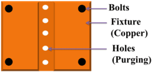
Fig 3 depicts the experimental set-up used to conduct the experiments. The welding torch is fixed while the workpiece moves at constant speed (controlled with speed knob) with the help of a rail guided motor (PUG machine) powered platform. The use of proper fixture is an essential requirement for producing a good weld joint. A suitable fixture is designed and constructed for the operation of welding procedure in open air to prevent both oxygen contamination and distortion of the workpiece. The backing plate of the fixture is also made of copper which results in high cooling rate, yielding low angular distortions of the joint. The provision for purging gas flow is essential for welding of titanium alloy. It helps to reduce the problem of oxidation due to high rate of heat transfer through copper as well as heat convection by the purging gas [4]. Secondary process parameters used for µ-PAW is depicted in Table 3.

Fig. 3 : Schematic of experimental set-up for µ-PAW used at IIT Guwahati.
Table 3 : Process parameters used for µ-PAW.
| Stand-off distance (mm) | 1.2-1.7 |
| Electrode diameter (mm) | 1.2 |
| Plasma gas flow rate (lpm) | 0.4-0.7 |
| Shielding gas flow rate (lpm) | 7-8 |
| Torch Position | Vertical |

Fig. 4 : Arrangement for provision of purging gas.
Microwelding of titanium alloy is investigated to find out the effect of heat input on thermal and mechanical aspects. The micro scale butt joint by plasma arc at optimal parameters is of very high quality, without any internal imperfections and with regular fusion zone. The maximum joint efficiency of the weld joint found to be more than 100% in most of the cases. The weld bead increases with current up to a certain limit after which burn out of the material occurs(beyond 9.5 A at welding speed of 2.33 mm/s and 2.75 mm/s, beyond 11.5 A at welding speed of 4.2 mm/s, beyond 12.5 A at welding speed of 5.62 mm/s).The temperatures are well below the vaporization temperature of the materials and hence it can be concluded that the conduction mode heat transfer prevails against keyhole formation within this power density range used for microwelding of 0.5 mm thick plate. It is also obvious that the heat affected zone is confined in small area due to effect of copper fixture. The distortion increases with increase in heat input due to greater amount of heat available at a specific area.The maximum measured deflection for the same welding condition of 4 mm/s and 11 A at a point 5 mm from end point along the weld line is about 3.45 mm [5-6].
SS 304 and low-carbon steel is successfully joined using μ-PAW process. The range of welding current shifts at the higher side during welding of low-carbon steel, due to the fact that higher thermal conductivity and diffusivity of low-carbon steel cause the deposited heat to diffuse away more rapidly. A low melting point as well as high heat capacity of SS304 (1723 K, 530 J/Kg K)makes the domain of the feasible weld narrow as compared to low carbon steel (1773 K, 510.78 J/Kg K). It is also observed that the weld bead of low-carbon steel is smaller for the same welding condition, but the total heat-affected zone is higher because low-carbon steel has very high thermal conductivity (43 W/mK) which causes most of the heat to dissipate away, whereas SS304 has lower thermal conductivity (16.2 W/mK) and the heat is highly concentrated (due to low thermal diffusivity- 4.2 µm2/s) in the weld zone causing it to form a wider bead [7].
A detailed study on themicrostructural changes of Maraging 300 steel (0.5 mm thick) weldments has been performed.The weldability of maraging steel with µ-PAW is accomplished by finding a set of suitable primary variables of welding current (7-14 A) and welding speed (2.8-3.7 mm/s). The HAZ is extended over a large area as compared to FZ. However, the structure of base material (BM) is not affected by diffusional heat transfer since the maximum temperature in this zone does not create any phase transformation. It clearly indicates the FZ and HAZ with long solidified grains at the boundary, which is the characteristic boundary condition for almost all kind of steels. The microstructure in the weld zone is primarily decided by the solidification behavior that critically assesses the size and distribution of grains, any segregation, porosity and hot-cracking behavior of the alloy [8].
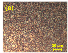
Inconel 718 sheets of thickness 0.7 mm welded joints is prepared using constant current (CC) and pulsed current (PC) micro-plasma arc welding process. Microstructure at the weld zone indicatethe dendrites for the PC mode of welding is very fine and equiaxed at the weld interior whereas the microstructure is coarser and columnar for CC mode of welding. Figure 5 depicts the microstructure at the weld interior for (a) PC mode and (b) CC mode. With decrease in welding heat input due to current pulsating, the cooling rate enhances resulting in a reduction in weld metal columnar dendrite arm spacing and size of the deleterious laves phase. PC mode weldments also show improvements in hardness and tensile properties as compared to the CC mode welding which is attributed due to reduce heat input and as a result the average cooling rate increases which further refines the fusion zone microstructure. This refined microstructure minimizes Nb segregation in the grain boundary and further diminishes the amount of laves phase. Nb-rich laves phase in the microstructure of weld fusion zone is undesirable because it results in detrimental effect on the mechanical properties [9]


Fig. 5 : Microstructure at the weld interior for (a) pulse mode and (b) continuous current mode welding [9].
Tailor welded blanks (TWBs) are manufactured by welding together sheets of different grades or thicknesses. TWBs are used to reduce the weight, which results in increase in fuel efficiency and reduction in cost due to use of less material. SS 316L (0.8 mm) and SS 310 (0.6 mm) is successfully joined in butt configuration to form a TWB joint. SS 316L is a variant of SS 316 with an extra low carbon that restricts detrimental precipitation of carbides. SS 316L finds applications in exhaust manifolds, evaporators, heat exchangers, furnace parts, jet engine parts, chemical equipment and parts exposed to marine atmospheres. SS 310 is a grade (highly alloyed) of austenitic stainless steel developed for high temperature services. Presence of high chromium and nickel composition allows this highly alloyed steel to withstand oxidation while in service at high temperatures (up to 1,200°C) in absence of reduced sulphur gases. SS 316L-SS310 joints enables to benefit of both the materials and enhance the property of the resulting structure [10].
Conclusions
The present article aims to summarize the research work carried out in Advanced Welding Lab, Indian Institute of Technology Guwahati. Following are the major conclusions from the present article:
- Effect of heat input on micro-plasma arc weldments on Ti6Al4V alloy with 500 µm sheet thickness is studied extensively. Optimum value of heat input results in joint efficiency comparable to base metal. Deformation behavior of the weldments at moderate heat input (~45-90 J/mm) is found to be relatively better than other welding conditions. This is attributed to low value of heat input resulting in high cooling rate(683 K/s)thus enhancing the microstructural properties, which results in improved mechanical properties, yielding high joint strength.
- Use of proper fixture is made to minimize oxidation and reduce distortion to considerable extent. Due to use of copper as fixture, high cooling rate (683 K/s) is achieved that lead to the formation of hard martensitic structure in micro-plasma weldments of Ti6Al4V alloys. As a result, the fracture toughness of the weld was lower than that of the parent material.
- A comparative analysis is performed based on the physical properties between SS304 and low-carbon steel. The behavior of the weld pool shape and size is mainly influenced by the thermal property whereas the residual distortion is decided by the solidification and mechanical constraints. The range of the current shifts at the higher side during welding of low-carbon steel (8-10 A for SS 304 whereas 8-12 A for LCS at welding speed of 2.75 mm/s), (10-15 A for SS 304 whereas 10-18 A for LCS at welding speed of 4.2 mm/s) and (11-18 A for SS 304 whereas 11-20 A for LCS at welding speed of 5.26 mm/s) i.e., for a similar condition, more current can be employed to obtain a successful joint. This is due to the fact that higher thermal conductivity and diffusivity of low-carbon steel cause the deposited heat to diffuse away more rapidly.
- Joining of maraging steel experiences broad metallurgical transformation that leads to welding distortion and transformation of austenite into martensite at very low temperature with significant increase in specific volume; that can be controlled by finding feasible range of process parameters. The microstructural study of maraging 300 steel welded samples provides the physical changes occurred during welding, and it provides the reasons for typical hardness profiles generated in the weld sample.
- Inconel 718 weldments in butt configuration are prepared using micro-plasma arc welding in pulse mode and continuous current mode. Further study on weld microstructure and mechanical behavior reveals that pulse mode results in significant refinement of fusion zone microstructure. Grain refinement minimizes the amount of brittle intermetallic laves phase in the weld zone, leads to significant improvement in the micro hardness value and tensile properties of the welded joint.
- Experimental analysis of TWB butt joint formed by µ-PAW process indicates that a weld joint with high quality, regular fusion zone and no visible flaw is obtained under controlled process parameters. Microstructure and solidification of the weld pool is a direct function of amount of heat input, which in turn dictates mechanical property of the resulting weld joint. Thus, selection of heat input value plays an important role for achieving sound weld joint. Micro-hardness of the weld zone is found to be higher than that of the base material and HAZ. This is attributed to the presence of fine grains in the weld zone which results in high value of joint strength and hardness but low value of ductility.
- The most influencing parameters are welding current and speed whereas plasma gas flow rate, stand-off distance, shielding gas flow rate, and electrode diameter are secondary parameters that influence the weld bead geometry and heat-affected zone. The combined effect of the parameters such as welding current and speed is represented by heat input per unit length (welding power/ speed). Too low heat input causes incomplete fusion or partial penetration that result in improper joint strength. If heat input is very high, the over-penetrated weld holds a large molten pool that may result in greater shrinkage and distortion. Therefore, the optimum combination of process parameters is necessary to achieve a sound weld joint.
Acknowledgement
The present investigation is a result of research work carried out by past and present researchers in Advanced Welding Laboratory, Department of Mechanical Engineering, Indian Institute of Technology Guwahati. The authors thankfully acknowledge the contribution of these researchers. The authors also gratefully acknowledge the experimental facility provided by the department of Mechanical Engineering, Central Workshop and Central Instrument Facility (CIF) at IIT Guwahati, Assam.
References
- H. P. Li and X. Chen: Three-dimensional modelling of a dc non-transferred arc plasma torch, Journal of Physics D: Applied Physics, 34 (2001) L99–L102.
- R. Sánchez-Tovar, M.T. Montañés, and J. García-Antón: Effect of the micro-plasma arc welding technique on the microstructure and pitting corrosion of AISI 316L stainless steels in heavy LiBr brines, Corrosion Science, 53(8) (2011) 2598-2610.
- C. S. Wu, L. Wang, W. J. Ren, and X. Y. Zhang: Plasma arc welding: Process, sensing, control and modeling, Journal of Manufacturing Processes, 16(1) (2014) 74-85.
- L. Z. Ming, S. L. Cui, Z. Luo, C. Z. Zhang, Z. M. Wang and Y. C. Zhang:Plasma arc welding: process variants and its recent developments of sensing, controlling and modelling, Journal of Manufacturing Processes, 23 (2016)315-327.
- M. Baruahand S. Bag: Influence of heat input in microwelding of titanium alloy by micro plasma arc, Journal of Materials Processing Technology, 231 (2016) 100 – 112.
- M. Baruah and S. Bag:Microstructural influence on mechanical properties in plasma microwelding of Ti6Al4V alloy, Journal of Materials Engineering and Performance, 25(11) (2016) 4718-4728.
- M. Baruah and S. Bag: Characteristic difference of thermo-mechanical behavior in plasma microwelding of steels, Welding in the World, 61(4) (2017) 857 – 871.
- T. Saikia, M. Baruah and S. Bag: On the effect of heat input in plasma microwelding of maraging steel, Proceedings of IMechE, Part B: Journal of Engineering Manufacture, DOI: 10.1177/0954405417731470.
- A. Sahu and S. Bag: Micro-plasma arc welding of Inconel 718 thin sheets (under review).
10. S. Dwibedi, S. Bag, D.K. Lodhi and A. Kalita: Joining of different thickness dissimilar materials SS 316L/SS 310 by µ-PAW process (under review).


