Cristian Delamarian,
ASME Authorized Inspector,
DP Industrie Service (Romania)
- Foreword
Welding represents an essential element in the process of power equipment fabrication. Nevertheless, this element has its special importance in the process of maintenance of this equipment as well. Sometimes, it represents the only option for keeping in service some critical components during the outage time [1], [2], [3]. In the last years, the importance of welding in this process increased significantly once the decrease of maintenance costs of the power equipment became an issue of a major importance. Initially used as a permanent joining method for replacing the damaged components, gradually, it became the basic element for the reconstruction of the initial shape, dimensions and operational characteristics of the damaged components. The paper presents several field applications of welding on the repair of damaged power equipment.
- Introduction in the welding engineering applications in the power plant maintenance
Power plant maintenance has a local strategic importance for the power plant itself, as well as general one for the whole economy of a region or even of a country. A very good example in this direction is the energy crisis that stroked Philippines at the beginning of 2010. Thus, following a long dry season and a pore raining season at the end of 2009, the month of January 2010 became for Philippines a critical time in its economic and social life. The hydropower plants which usually deliver 25-30 % of the power demand in Philippines were forced to shut down their units because of the above mentioned reasons in order to save the water resources in their reservoirs for water supply purposes of the population in Manila and in the surrounding areas. Consequently, the thermal power plants were forced to cover the energy demand through out a total availability of their units.
In order to comply with such a critical demand coming from the client side (sometime even from the government side), which requires the plant to operate in base load system at its full load for long periods of time, one should ensure that the equipment is able to operate at the design parameters for at least the period of time between two consecutive planned outages.
Replacement of the damaged equipment which no longer partially or totally fulfills its designed functions represented so far a usual option. Considering the novel welding technologies, materials, and equipments as well as tougher and tougher conditions where these solutions can apply, the alternative of repairing this equipment became the first option.
The advantages of this alternative are numerous. Among others one may mention the following:
- Shortening the time of restoring the dimensions and operating capabilities of the component;
- Reducing the stock of the spare equipment from the power plant ware house;
- Relaxing the planning process of the damaged equipment replacement, temporary or permanently repair becoming the first option;
- Huge savings of the power plant maintenance costs.
On the other side, there are some limitations as well of this solution:
- Some components may be strongly damaged beyond any repair;
- Some weld repair methods are complicated to apply or the weld quality hard to evaluate (e.g. because of lack of physical space);
- Weld repair may require sometimes Post Weld Heat Treatment, operation hard or even impossible apply to some heavy big or complicated components;
- A weld repaired component sometime cannot anymore be compared with a new one, the first one could anytime suffer during plant operation damages at much higher rates just because of the weld repair.
Nevertheless, despite the all disadvantages, the weld repair will win more and more supporters among the power plant maintenance personnel in the coming years.
- Field applications of the welding in power equipment maintenance
Following, one shall discuss some examples of field applications of welding in the power plant maintenance. Approached subjects shall exclude the investigations conducted for the assessment of damage causes, this subject being beyond the purpose of this presentation. The paper will be oriented exclusively on the repair approaches and will include the judgment that supported each technical solution separately in order to describe to the reader the internal mechanisms of these complex processes.
3.1. Example 1: Weld repair of a steam coil air heater flash tank
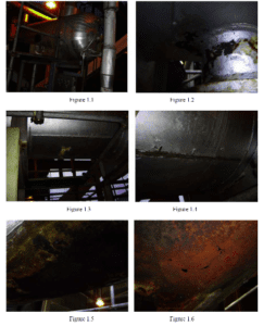
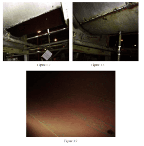
A Steam Coil Air Heater Flash Tank (see Figure 1.1) was found severally damaged during a regular annual inspection (see Figure 1.2). It was also found that a big patch was welded at the bottom the tank (see Figure 1.3) to compensate wall thickness losses recorded couple of years ago. Analyzing the situation, it was taken the decision to remove the old patch (see Figure 1.4) in order to thoroughly check the existing situation. The results of this approach revealed through-wall penetrated corrosion damage (see Figures no. 1.5 and 1.6). The damaged area was cut off and replaced. The vessel shell was initially made of carbon steel plate. Considering the severe damage encountered only after 8 years of operation, the replacement of damaged are with a stainless steel plate was considered.
The plate (8 mm thick) was rolled and a Vweld preparation fabricated (see Figure 1.7). It was chosen a WPS combining PNo. 1 (carbon steel) with P-No. 8 (stainless steel) base materials with one side, fully penetrated weld with no backing support (see Figure 1.8). It was performed by means of SMAW using stainless steel electrodes and the WPS was qualified according to ASME Section IX rules [4]. After 2 years in operation a visual inner side inspection revealed no problems related with the quality of this weld (see Figure 1.9).
3.2. Example 2: Weld repair of an auxiliary cold reheat desuperheater pressure control valve
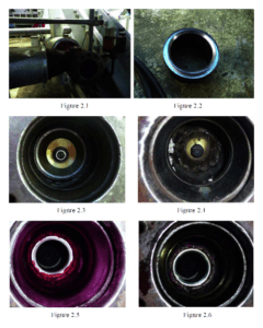
An Auxiliary Cold Reheat Desuperheater Pressure Control Valve was found severely damaged during boiler operation. Any actions on closing this valve during operation had no significant results. Therefore, during boiler shutdown, the valve was disassembled (see Figure 2.1) and the valve seat was found severally damaged. The solution chosen was to remove the old seat and replace it by means of welding with a new one (see Figure 2.2). There was a problem on conducting this procedure, namely the valve body was made of P-No. 4 material which normally requires PWHT. In order to avoid PWHT which was not applicable because of logistic circumstances at the time of weld repair, a WPS using a Ni-based alloy without PWHT was used. The new seat was fit in its location and the seat surface was protected by a metal cap (see Figure 2.3). Once the weld was finished (see Figure 2.4), PT was conducted on the repaired surface (see Figure 2.5). Unfortunately, properly conducting PT was a real challenge because of space limitations (see Figure 2.5). Nevertheless, the PT revealed no cracks in the new seat which was the biggest issue on this procedure. The rest of the weld was visually checked for cracks (the PT results were beyond any acceptable interpretations) and it was taken the decision that no visually detectable defects were found in this seal weld.
Therefore, a blue ink check (see Figure 2.6) was conducted to assess the sealing capability of the valve, test which was passed successfully. This test confirmed the proper orientation of this seat perpendicularly to the disk axis.
3.3. Example 3: Weld repair of a boiler heater
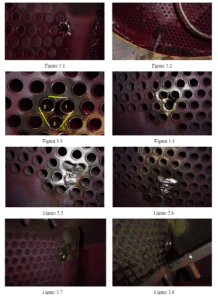
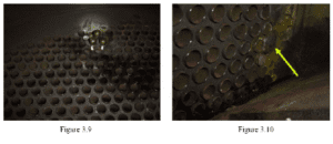
During a regular annual outage a Heater was opened because of leaking reported by the operation people, encountered during boiler operation. Following the visual checking severe damage of the tube plate was noticed. In order to thoroughly check the damage extension, it was decided to conduct a pressure test at 100 psi on the shell side. Two leakages were encountered during this test (see Figures no. 3.1 and 3.2). It was chosen the weld repair as the only alternative solution for this problem. The damaged area was grinded in a triangle shape to allow weld repair to be conducted in this tight location (see Figures no. 3.3 and 3.4). The tubes no. 1, 2, and 3 were cut below the surface of the tube plate about 50 mm deep (see Figure 3.4). Further on, all three tubes were plugged. The plugs were fixed at least 25 mm deep under the tube plate surface. The tube plate material was P No. 1 (carbon steel) and the thickness was about 173 mm. The tubes material as well as the plugs material was P No. 8 (stainless steel). Once the plugs were fixed in their places, the weld repair with stainless steel weld metal was conducted (see Figures no. 3.5 and 3.6). All ends of the leaking tubes on the upper half as well as on the lower half of the heater were plugged (see Figures no. 3.7, 3.8, and 3.9) and the plug heads were cut at the tube limit level and than completely welded (see Figure 3.10).
3.4. Example 4: Weld repair of a steam control valve
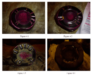
A Steam Control Valve was reported to have a pore operation during boiler functioning and therefore it was disassembled and checked. The valve was found to have on both sides of the disk steam cuts in several locations. Because of lack of spare parts, it was decided to conduct a weld repair on the valve disk. Thus, the cracks were completely excavated by grinding (see Figures no. 4.1 and 4.2) and a weld repair was conducted after that.
The weld repair consisted of one buttering layer done by means of GTAW with a stainless steel wire and a completion weld with a hard facing electrode by means of SMAW (see Figure 4.3) [4]. After the weld repair, the disk was machined and lapped at its initial shape (see Figure 4.4).
3.5. Example 5: Weld repair of some elements on boiler feed pump recirculation line
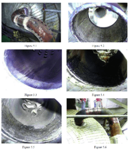
UTG (UT thickness measurements) were conducted on a Boiler Feed Pump (BFP) recirculation line, on two elbows and a straight section (spool) before entering into the Deaerator Storage Tank – DST – (see Figure 5.1) in order to monitor the erosion process taking place here. The measurements were compared than with the ones from last years obtained on this line. Considering the UTG results on the elements of the BFP Line, it was recommend the replacement of the spool between the two elbows entering the DST.
Furthermore, considering the fact that the new spool was only available as a carbon steel material, an inner stainless steel overlay was recommended to be performed in order to avoid further erosion of this section (see Figure 5.2).
The same solution was recommended for the discharge section entering into DST which was found also eroded (see Figures no. 5.3, 5.4, and 5.5). After inner side weld overlay of the spool, and reweld of the spool on its initial place, PT and UT flaw detection were conducted on these new welded joints (see Figure 5.6). After NDT passed, UTG measurements were taken from the replaced sections of the pipe as “0” reference for future measurements comparison basis.
- Conclusion
As one may see from the above examples, the applications of welding in power plant maintenance activities are very diverse. Welding technique and weld material are selected on a case-by-case basis. Proper selection of the weld material is an essential ingredient in the success of the weld repair and therefore, it requires a proper judgment before taking this decision. Component operating parameters and conditions must also be considered during the weld metal selection.
Welder’s skills are becoming of a growing importance. PWHT became more as an “option” instead of a “must” basically because of a huge advantages given by the weld material applications. Currently, there are only few situations during a major shut down of a usual 10 years old 460 MW unit which requires component replacement as the only alternative. Furthermore, weld repairs initially thought as temporary solutions, were found to be as good as the replacement one, and therefore, repaired components are no longer replaced in due course but just monitored at regular time intervals.
References
[1] Cristian Delamarian – Manual pentru mentenanţa şi retehnologizarea instalaţiilor termoenergetice şi industriale, Ed. Sudura, Timişoara,
1999
[2] API 579 – Fitness for Service, January 2000
[3] API 580 – Risk Based Inspection, 2000.
[4] ASME Section IX – Welding and Brazing Qualifications, 2007
Edition, 2009 Addenda
[5] ASME Section XI – Rules for Inservice Inspection of Nuclear Power
Plant Components 2007 Edition, 2009 Addenda


