

G. N. Silva 1, K. Faes 1, J. Feyaerts 1, L. Adinolfi 1,2, J. Romo 3, J. Lamontanara 4, P. Perlo5
1 : Belgian Welding Institute, Ghent, 9050, Belgium.
2 : University of Salerno, Fisciano, 84084, Italy.
3 : Interactive Fully Electrical Vechicles, La Loggia, 10040, Italy.
4 : MA srl, Gruppo CLN, Rivoli, 10098, Italy.
5 : Cidaut, Boecillo, 47151, Spain.
ABSTRACT. This paper describes the results of MAG welding trials of the dual phase steel DP800, and the examination of those joints. The test coupons consisted of hollow square profiles with a thin wall thickness of 1.3 and 2 mm. The experiments were carried out with a welding robot as well as manually in the butt weld configuration.
Detailed results concerning optimised welding parameters, metallographic examination of the welds, hardness examinations, tensile as well as fatigue testing are discussed. It was found that due to the thin wall thickness and the square shape of the specimens, there was a high risk that the specimens became saturated with welding heat at, resulting in burn-through of the weld. When welding parameters resulting in a low heat input were applied, other weld defects appeared.
An important conclusion that can be drawn is the decrease of hardness in the heat affected zone next to the base material. Tensile tests carried out on welded joints showed that the tensile specimens failed in this soft heat affected zone at values significantly lower than the tensile properties of the base materials. This article also discusses various tests designed to minimise this detrimental effect of softening in the heat affected zone. Fatigue tests were also carried out. The effect of misalignment in combination with the geometrical shape of the weld was clearly noticed in the results.
- Introduction
The European project STEEL S4 EV [[i]]aims at developing a light and safe electric vehicle for passenger transport in the city. The project contributes to the utilisation of high strength steels by researching and developing an innovative chassis for electric vehicles. This must comply with structural and safety requirements and will be the backbone for the design of a new generation of electric vehicles, that will demonstrate safe lightweight performance combined with optimised LCA indicators.
Dual Phase (DP) steels are used in this development. These are innovative materials that obtain their properties through a unique structure consisting of two phases (ferritic-martensitic microstructure).
The Belgian Welding Institute investigated the welding of these materials. DP steels are weldable, but often the microstructure is destroyed as a result of the weld cycle. Weld joint design and welding methodologies were investigated to maintain the material properties in the weld area, assuring robustness and long term durability.
The optimal welding parameters were investigated, whereby an acceptable weld quality is obtained without too many implications for the mechanical properties.
The following aspects were examined
- influence of the weld cycle on the softening in the heat-affected zone,
- influence of the filler metal,
- influence of forced cooling after welding.
- Welding of High Strength Steels
2.1.Introduction :
Advanced high strength steel (AHSS) is the fastest growing material group in today’s automotive industry, because of its high strength to weight ratio performance, which allows the car makers to produce thinner components and, thereby, reduce the fuel consumption [[ii],[iii],[iv]].The Dual phase (DP) steel group is among the AHSS family widely used in the crash zones of the vehicle due to its high energy absorption ability [4,[v],[vi]].
In order to take advantage of the excellent properties of AHSS, processing skills with these materials must be enhanced and problems related to these steels should be overcome. For instance, high susceptibility to cracking and heat affected zone (HAZ) softening are significant problems that can affect the efficiency of the welded joint and the product[[vii]].
2.2. Welding of AHSS
The high strength of AHSS is achieved by modifying the steel microstructure. This involves that the microstructure may change as a result of the heat input during welding. The welding heat input is consequently a critical issue significantly affecting the joint strength and properties. If the heat input is too low, there is an increased risk of lack of fusion. If the heat input is too high, the heat affected zone gets too large, which can cause detrimental effects within the weld. Heat input is also a very important variable governing the cooling time (t8/5; the higher the heat input, the slower the cooling rate), which has a key role in the phase balance and mechanical properties of the HAZ and weld. In practice, the cooling rate is dependent on many factors: heat input, process efficiency, material properties preheat temperature, material thickness and wire feeding rate. For arc welding processes, heat input can be controlled by adjusting the welding current, welding voltage and welding speed and it can be defined as a distributed heat flux on the weldment surface.
Studies of the weldability of AHSS have shown that maximum softening occurs in the microstructural area of the HAZ where the peak temperature during welding reaches the lower critical temperature (Ac1) of the steel. This is typically referred to as HAZ softening in the subcritical area, i.e., the zone in which the temperature is too low to cause ferrite-austenite transformation but high enough to temper the martensite present in the base material microstructure. The tempered or subcritical HAZ (SC-HAZ)exhibits a lower hardness vs. that of the base material. Decomposition of martensite due to high tempering causes the soft area in the HAZ. Figure 1 shows a typical softened area in the HAZ of an AHSS [[viii]].
[[i]] : Project website : http://www.steel-s4-ev.eu/
[[ii]] : Kuziak, R.; Kawalla, R.; Waengler, S. Advanced high strength steels for automotive industry. Arch. Civ. Mech. Eng. 2008, 8, 103–117.
[[iii]] : Ebrahimi, F.; Saeidi, N.; Raeissi, M. Microstructural modifications of dual-phase steels: An overview of recent progress and challenges. Steel Res. Int. 2020, 91, 200178.
[[iv]] : Lesch, C.; Kwiaton, N.; Klose, F.B. Advanced high strength steels (AHSS) for automotive applications – Tailored properties by smart microstructural adjustments. Steel Res. Int. 2017, 10, 1700210.
[[v]] : Senuma, T. Physical metallurgy of modern high strength steel sheets. ISIJ Int. 2001, 41, 520–532.
[[vi]] : Ishikawa, T. Understanding and controlling microstructural evolution in metal forming: An overview. In Microstructure Evolutionin Metal Forming Processes, 1st ed.; Lin, J., Balint, D., Pietrzyk, M., Eds.; Woodhead Publishing Ltd.: Cambridge, UK, 2012;Volume 1, pp. 3–16.
[[vii]] : P. Kah, M. Pirinen, R. Suoranta, J. Martikainen, Welding of Ultra High Strength Steels. Advanced Materials Research. Vol 849. 2014. doi: 10.4028/www.scientific.net/AMR.849.357
[[viii]] : Xia, M., Biro, E., Tian, Z. and Zhou, Y., 2008, “Effect of heat input and martensite on HAZ softening in laser welding of dual phase steels,” ISIJ International Journal, 48 (6) pp. 809-814.

Figure 1 – Hardness profile across the weld: Nd YAG laser welding of DP980 with speed of 6.0 m/min.
Due to the specific properties of AHSS steels, the welding parameters and especially the heat input, have to be controlled, due to the risk of cracking and the HAZ softening phenomena, as illustrated schematically in Figure 2. The shaded area in Figure 2 shows that the permissible heat input is limited by the risk of cold cracking and excessive hardening on the left, and on the right, a loss of strength and hardness due to over-tempering and possible loss of toughness, as a result of re-transformation to upper bainitic microstructures during cooling [[i]].

Figure 2 – Total weld heat input relationship for welding UHSS steels.
Despite the susceptibility to cracking and softening phenomena in the HAZ and the weld metal of AHSS, these steels can be welded effectively, but the heat inputduring welding must be precisely controlled, in order to avoid excessive hardening and subsequent cold cracking, in case of a short cooling time, or to avoid reduced strength properties, especially in the HAZ, in case of an excessive heat input or a slow cooling rate. It should be emphasized that when welding AHSS, the heat input during the welding process must be kept as low as possible to avoid excessive softening.
According to the characteristics inherent to the different welding processes, some become more easily applicable for welding of AHSS steels. Table 1 presents a summary and comparison of key considerations and characteristics of some of the most used welding methods, while Table 2 presents a summary and comparison of the different AHSS materials with different welding processes.
Table 1 – Comparison different welding methods for AHSS.
| Shielded metal arc welding | MIG/MAGwelding | TIG welding | Laser beam welding | |
| Process complexity | Low | Low | Medium | High |
| Heat input | Low | High | High | Low |
| HAZ | Relatively small HAZ, low softening | May have large HAZ and high softening | May have large HAZ and high softening | Small HAZ, low softening |
| Welded joint properties | – | Good strength and mechanical properties are possible | Good strength and mechanical properties are possible | Good strength, but poor weld properties may occur |
Table 2 – Different welding processes using different AHSS [i].
| Steel type | Shielded metal arc welding | MIG/MAG welding | TIG welding | Laser beam welding |
| Transformation Induced Plasticity (TRIP) | – | Weldability is good | – | Yttrium-aluminium-garnet for TRIP780 is good. |
| Twinning Induced Plasticity (TWIP) | – | Weldability is good | – | – |
| Martensitic Steel (MS) | – | Weldability is good | – | – |
| Dual Phase (DP) | – | Good weldability for MIG/MAG, HAZ softening | – | Excellent weldability, low heat input |
| Complex-Phase (CP) | – | Weldability is good | – | – |
| Ferritic-Bainitic (FB) | Weldability is good | Weldability is good | Weldability is good | Weldability is good |
| Quenced and Tempered (QT) | Weldability is Good | Weldability is good | Weldability is good | Weldability is good |
| Thermo-mechanically controlled processed (TMCP) | Weldability is good | Weldability is good | Weldability is good | Weldability is good |
MIG/MAG welding of high strength steels
The use of arc welding processes for AHSS have not been completely investigated yet. Some authors preliminary investigated arc welding (MIG/MAG) of AHSS (such as DP steels) by evaluating the microstructural and mechanical joint properties, as well as considering the effects of microscopic welding defects on the tensile strength and the fracture mode of welded samples[[ii],[iii]].In particular, the larger heat input involved during arc welding makes this joining process more problematic than spot and laser welding techniques. This is mainly due to the difficulty to limit thermal deformation of sheets, welding defects (such as burn through and cracks) and excessive heating of the substrate materials (i.e. large heat affected zones).
In [5], the weldability of dissimilar AHSS steels was investigated. The heat input was varied at 3 levels, and overmatched filler wires were used. The welds were investigated using hardness tests, SEM and NDT X-ray spectrum mapping in order to observe the hardness behaviour and the microstructure precipitations in the HAZ of the welds.
For dissimilar MIG/MAG butt welds of DP600 and TWIP steel sheets, they observed a fully martensitic microstructure, in the DP side of the heat affected zone close to the fusion zone and subcritical tempering of the martensite in the HAZ close to the base material DP600.
The fracture during tensile testing mostly occurred in the fusion zone, at a stress level of about 10% lower than the DP base material ultimate tensile strength.
If the strength of the base material is higher, more softening phenomena will occur [[iv]]. This is for example the case with DP steels with a high martensite content and a strength of more than 800 MPa, due to small soft zones in the HAZ. More martensite islands in the base material results in more tempered martensite after welding.
Improvement of MIG/MAG welded joints of DP steels is possible by increasing the cooling rate. Static tensile tests on butt welded DP780 demonstrated that a higher cooling rate results in a better joint efficiency and a slightly higher strain at the peak load. All welds failed in the softer HAZ region[[v]]. In this publication, different cooling techniques in flash butt welding of Mn-Cr-Mo dual-phase steel were investigated; normal machine cooling, forced air cooling and water spray cooling. The work showed a lower degree of HAZ softening (measured by microhardness testing) in spray cooled samples.
- MATERIALS AND METHODOLOGY
3.1. Materials
The material used for the welding trials is the Dual-Phase steel DP800. The chemical composition as well as the mechanical properties of the base material is shown inTable 3 and Table 4.
Table 3: Chemical compositionsof DP800
| % wt | C | Mn+Al+Si | P | S | Cu | Ni | Cr+Mo | V+Nb+Ti |
| DP800 | 0.157 | 2.43 | 0.009 | 0.0020 | – | – | – | 0.0043 |
Table 4: Mechanical properties of DP800
| Tensile strength “Rm”
[MPa] |
Yield strength “Re”
[MPa] |
Elongation “El”
[%] |
|
| DP800 | 868 | 668 | 14.0 |
3.2. Specimen design
For the test samples, square profiles were used, with dimensions of 40 × 40 mm, and with 2 wall thicknesses; 1,3 and 2 mm Butt welds using robotic and manual welding were realised using these specimens.
3.3. Equipment
The welds were performed with the following equipment for robotic welding:
- KUKA KR 8 R2010-2 robot with KR C4 control unit
- Power source: Fronius TransPuls Synergic 5000 (CMT); liquid cooled, pulse welding 500 A (40%) and 360 A (100%),
- Wire feeder: Fronius VR7000,
- Welding torch: Fronius Robacta Drive CMT, liquid cooled; push pull,
- KP1-HC single-axis positioner with horizontal rotational axis with welding table with fixing possibilities mounted in between.

Figure 3: Overview of MIG/MAG equipment used for the robotised welds
Manual welds were performed with the following equipment:
- Power source: Fronius TransPuls Synergic 5000
- Wire feeder:FroniusVR7000
High-strength filler material was used; EN ISO 16834-A : G 69 4 M Mn3Ni1CrMo – Ø0.8mm.
3.4. Welding procedure
For the butt welds, the test specimens were fixed under an angle of 45° and welded in 2 sequences as shown in Figure 4. The samples to be welded were positioned in the butt welding configuration, separated with a gap of approximately 0.5 – 1.0 mm.

Figure 4: Welding sequence for butt weld tests
The process window (weldability lobe) was determined by 2 limits: welding parameter settings providing a high heat input that resulted in a burn-through, and settings providing a low heat input that resulted in lack of fusion. Both defect types are shown in Figure 5.
These defects are caused due to the parameter settings and deviations of the tube dimensions, resulting in a linear misalignment of the tubes. This effect appeared in most joints. When 2 sides of the tubes were aligned against each other, the other two sides of the tubes showed in most cases a misalignment. This is caused by the tolerances on the tube dimensions. Especially for the robotic welded trials, a detrimental effect could be observed due to this. A metallographic cross section of a weld with a misalignment is shown in Figure 6.

Figure 5: Limits of the parameter settings (heat-input)in a butt joint :Left: Lack of penetration; Right: Burn-through
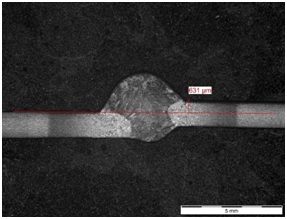
Figure 6: Metallographic cross section of a weld a misalignment
In order to examine the influence and relevance of quenching the weld in water on the weld hardness, specific trials were executed. Quenching was obtained due to forced cooling in water directly after welding or by cooling during welding.
For these experiments, 2 sets of thermocouples were attached at the outer tube surface, in the SC-HAZ of the specimens to be welded (see Figure 7), one set at weld #3 and one at weld #4 (cfr. Figure 4). The exact location of this zone was determined due to previous metallographic sections and hardness measurements. Immediately after welding, the welded parts were released out of the jig and manually submerged in a recipient filled with water at room temperature.

Figure 7: Experimental set-up of DP800 with thermocouples attached at the location of the soft fine-grained HAZ
Also experiments were conducted to examine if cooling during welding has an effect on the hardness values. For these experiments, a copper block was machined to fit over one of the tubes to be welded. The objective is to enhance the heat-sink effect in the tubes during welding. Again, a set of thermocouples was attached at the outer surface of the tubes, in the SC-HAZ. The thermocouples were always fixed at weld sequence #4 (see Figure 4, left). The copper block was put as close as possible to the joint without interfering the torch (see Figure 8).

Figure 8: Experimental set-up of the copper block on the tubes (DP800)
- EXPERIMENTAL RESULTS AND DISCUSSION
4.1. Metallographic examination
The microstructures of the base material of DP800 (Figure 9) consists of dual phase ferrite and martensite. The ferrite grains are white, while the martensite islands are the dark fields(region 1 in Figure 9). Next to the base material,theSC-HAZ can be noticed (region 2 in Figure 9). This zone has similar phases in the microstructure compared to the base material. Apparently, some amount of recrystallisation took place since the microstructure is much more fine-grained. Next to the weld, a coarse-grained heat-affected zone can be noticed (region 3 in Figure 9). The microstructure consists of large pre-existing austenite grains with a lath-like martensitic structure. The microstructure of the weld metal (region 4 in Figure 9) depends on the combination base material/filler material. Nevertheless, itsmicrostructure is always martensitic. The different zones are shown in Figure 9 and Figure 10.


4.2. Hardness examination
For the hardness examination, one row of indentations was made across the welded zone at mid thickness of the tube wall (see Figure 11), using a 1 kg load for 15 seconds. The distance between the indentations was 0.5 mm.

In the SC-HAZ, the hardness decreases to a minimum. The hardness in this zone is around 190-200 HV which is 30% lower than the base material hardness of DP800 (270-280 HV). The hardness values observed in this zone suggests that the martensite in this zone is softened due tempering (see Figure 12).
In the HAZ between the SC-HAZ and the fusion line, the hardness increases. The hardness in this zone depends on the type of material and on the welding method (manually or robotised). The joints welded with the robot show a higher hardness in this zone than the manually welded joints. The hardness difference between robotic and manual welding is about 20 HV (250 HV for robotic and 230 HV for manual welding). This difference can be explained by the fact that the heat-input for robotic welding is lower than for manual welding. This implies that the cooling rate for robotic welding is higher, which may result in a higher hardness in this zone.
Close to the fusion line, in the coarse-grained heat affected zone, the hardness drops again to a similar value of approximately 230-240 HV. It should be mentioned that the hardness drop was less pronounced for manually welded joints (about 10 HV).
A comparable effect was noticed for the hardness of the weld metal. The weld metal hardness of robotic welds is higher than for manual welds, which shows a hardness decrease of about 40 HV (290 HV for robotic and 250 HV for manual).

Figure 12: Results of the hardness measurements
Influence of forced cooling during welding
Figure 13 shows the temperature curve of weld sequence #4 in the SC-HAZ. As can be seen on the curve, the impact of the copper block on the heat-sink effect is apparently rather negligible (minimal difference between both temperature profiles).
The use of the copper blocks didn’t influence the hardness values either, compared to the hardness values of the as-welded samples (see Figure 15).The hardness in the SC-HAZ was around 200 HV, which is the same value as the welds performed without the use of a copper block.
The limited influence can be explained by the fact that the quenching effect starts relatively late. After all, for welding sequence #4 the temperature in the SC-HAZ has already decreased to 600°C when quenching starts. An improved result can be expected if quenching is performed earlier after welding, but this is not always possible for practical reasons.

Figure 13: Temperature curve for weld #4, using a copper block (red) and without a copper block (blue)
Influence of quenching after welding
The measured temperature curve is shown in Figure 14. A maximum temperature of 750°C was reached for both weld sequences #3 and #4. Quenching in water started about 7 seconds after the maximum temperature duringthe last weld was reached. The temperature of weld sequence #4 at the start of quenching was 610°C.

Figure 14: Temperature curve of quenching DP800
The hardness in the SC-HAZ of the tubes which were quenched after welding was about 40-50 HV higher than the as-welded samples. This means that water quenching partially stops the tempering of the martensite. The biggest effect however could be observedin the weld metal hardness. After quenching, the weld metal hardness was about 420HV, while this was only 290 HV in the as-welded samples.

Figure 15: Hardness traverse: without forced cooling during welding (as-welded; grey curve), water-quenched after welding (orange curve), cooled during welding with copper block (green curve)
4.3. Tensile testing
Tensile test samples were extracted from each side of the welded tubular parts, excluding the side with the longitudinal weld (see Figure 16). At least 3 tensile test specimens were prepared and tested for each welding condition. Subsequently, the average was calculated out of these tests and reported.
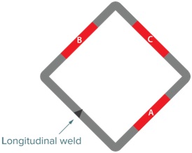
Figure 16: Sampling for mechanical testing
Tensile tests were carried out according to EN ISO 4136 ”Destructive tests on welds in metallic materials – Transverse tensile test” , using a 25 kN Instron servo-hydraulic universal testing machine equipped with data acquisition and hydraulic pressure grips. Testing was carried out at room temperature. The test specimens were extracted from the welded samples in such a way that the weld was positioned at the centre of the gauge length. Subsequently the sharp edges were removed to avoid any influence on the test result.
In all cases, failure occurred in the SC-HAZ (see Figure 17). This observation is supported by the conclusion of the hardness examination; the zone with the lowest hardness is the zone where the tensile strength is the lowest and failure occurs.

Figure 17: Metallographic section of a failed tensile specimen – DP800, welded manually.
Constriction due to tensile testing was observed at the non-failed side of the weld (between arrows)
Compared to the base material, the tensile strength of the welded samples is significantly lower. A reduction of about 18-23% was observed. A difference could be noticed between the manually welded samples and the samples welded with the robot.The heat-input for manually welding was typically higher than for robotic welding. In fact, a higher heat-input results in lower hardness values in the SC-HAZ next to the base material and thus a zone with a lower tensile strength.
Additional tensile tests were performed on 3 full-scale samples welded with optimised parameters. Figure 18, left shows the test-setup and the 3 test specimens after testing are shown in Figure 18, right. The average tensile strength obtained for the joints (696 MPa) is of the same order of magnitude as the average tensile strength determined using standardised flat tensile test specimens(715 MPa).

Figure 18: Tensile test set-up of full-scale specimens. Set-up (left) and tested samples (right)
4.4. Fatigue testing
The equipment and test conditions described in the previous paragraph were also used for fatigue testing. The fatigue tests were executed according to ISO/TR 14345 ”Fatigue – Fatigue testing of welded components – Guidance”.
The applied test plan for fatigue testing is detailed below:
- number of stress ranges tested: min. 3
- determination of stress range: related to the YS achieved with the tensile tests (with a minimum nominal stress of 200 MPa)
- number of samples/stress range: 3
- frequency: 20 Hz
- stress ratio (R; (σmin/σmax): 0.1, with a sinusoidal waveform.
The fatigue testing results for the different material combinations are visualized in the S-N curve shown in Figure 19.
It can be seen that there is a rather large scatter on the results, resulting in a large standard deviation of correspondingly 0.412. For high strength steels, a standard deviation of 0.162 is generally accepted [[i]]. This large scatter is probably caused by the influence of the misalignment as well as the presence of hot-spots. These hot spots are stress concentrations located at the weld toe, caused by the geometrical shape of the welded joint(presence of the weld cap and the weld root in the as-welded condition; see Figure 20, right). Hot-spots cause an increase of the nominal stress due to the geometrical shape of the welded joint. Due to the variety in weld geometry and the effect of this on the fatigue resistance, hot-spots cause a difference of the maximum stress present at the hot-spot in a set of fatigue test specimens where an equal nominal stress was applied, resulting in the scatter described above.
Misalignment (see Figure 20) is detrimental because a bending component is added to the (tensile) dynamic loads.
For the material combination DP800 1.3 mm – DP800 1.3 mm, a linear regression was applied and is shown in Figure 19(the red line). This line corresponds with a probability of 50% (mean SN curve). When projected to the aimed nominal stress of 200 MPa, there is 50% chance that 500.240 load cycles will be achieved, as defined by the S/N curve,.

Figure 19: S-N curve

Failure occurred sometimes in the weld but in the majority of the failed samples, failure occurred at the weld toe or the hot-spot (see Figure 21).

Figure 21: Example of the failure location (weld toe) which was noticed in the majority of the fatigue specimens. Sample also shows a misalignment
In order to overcome the detrimental effect of the hot-spots, also fatigue tests were performed with flushed specimens (over-thickness of the weld cap and weld root was removed). These tests showed that no significant improvement of the fatigue resistance could be obtained. This can be explained by the presence of the hot-spots, which are still present due to misalignment, even after flushing (see Figure 22) as well as the detrimental effect of the misalignment itself, since flushing does not have an influence on the alignment of the tubes. Also, it should be mentioned that the fatigue tests on flushed specimens were carried out at relative high stress levels. The positive effect of flushing regarding the fatigue resistance might be reflected with lower applied nominal stresses.

Figure 22: Flushed specimen with still existing weld toes due to misalignment (sketch and welded specimen)
- CONCLUSIONS
The weldability of the DP steel DP800 using robotised and manual MIG/MAG welding in a butt joint configuration was acceptable. However, the reproducibility of the welding results showed 2 major limits:
- Burn-through: a collapse of the weld pool could be noticed.
- Lack of fusion/root penetration: when the heat-input was decreased, the risk of lack of fusion and lack of root penetration increases.
It could be noticed that the fit-up is essential to limit the risk of burn-through. Besides burn-through, a higher heat-input also results in a mechanically weak location in the heat-affected zone directly next to the base material (SC-HAZ), resulting in a lower hardness and a lower tensile strength of the joint. In order to minimize this effect, welding tests were performed with lower heat-inputs. However, lack of fusion was noticed when the heat-input was too low. Additional tests performed to increase the cooling rate by quenching in water after welding and thus the formation of martensite in the SC-HAZ, showed an increase of the hardness in the SC-HAZ of about 25%. A larger effect can be expected when the time between welding and quenching can be reduced. Nevertheless, quenching also raises the hardness of the weld metal withabout 45% compared to as welded specimens.
The fatigue tests showed scattered results regarding the fatigue resistance of the welded hollow sections due to the combination of local misalignment of the parts and the presence of hot-spots (transition of weld metal/base material). In most cases, fatigue failure occurs in these hot-spots. Hot-spots can be reduced when the weld cap and weld root are flushed, however misalignment depends on the tolerances of the profiles to be welded. During the tests, it could be noticed that alignment of 2 sides of the profiles resulted sometimes in a large misalignment of the 2 other sides. In this case, flushing of the weld cap and root does not eliminate the hot-spots entirely which implies that the weak zone for fatigue strength is still present.
- Acknowledgments

The Project has received funding from the Research Fund for Coal and Steel (RFCS) under grant agreement nº 800726. The RFCS provides funding for high quality Research, Pilot and Demonstration projects which support the competitiveness and sustainability of the European industries.
- References
: Project website : http://www.steel-s4-ev.eu/
[[1]] : Kuziak, R.; Kawalla, R.; Waengler, S. Advanced high strength steels for automotive industry. Arch. Civ. Mech. Eng. 2008, 8, 103–117.
[[1]] : Ebrahimi, F.; Saeidi, N.; Raeissi, M. Microstructural modifications of dual-phase steels: An overview of recent progress and challenges. Steel Res. Int. 2020, 91, 200178.
[[1]] : Lesch, C.; Kwiaton, N.; Klose, F.B. Advanced high strength steels (AHSS) for automotive applications – Tailored properties by smart microstructural adjustments. Steel Res. Int. 2017, 10, 1700210.
[[1]] : Senuma, T. Physical metallurgy of modern high strength steel sheets. ISIJ Int. 2001, 41, 520–532.
[[1]] : Ishikawa, T. Understanding and controlling microstructural evolution in metal forming: An overview. In Microstructure Evolutionin Metal Forming Processes, 1st ed.; Lin, J., Balint, D., Pietrzyk, M., Eds.; Woodhead Publishing Ltd.: Cambridge, UK, 2012;Volume 1, pp. 3–16.
[[1]] : P. Kah, M. Pirinen, R. Suoranta, J. Martikainen, Welding of Ultra High Strength Steels. Advanced Materials Research. Vol 849. 2014. doi: 10.4028/www.scientific.net/AMR.849.357
[[1]] : Xia, M., Biro, E., Tian, Z. and Zhou, Y., 2008, “Effect of heat input and martensite on HAZ softening in laser welding of dual phase steels,” ISIJ International Journal, 48 (6) pp. 809-814.
[[1]] : AWRA, 1985, (Australian Welding Research Association now WTIA Welding Technology Institute of Australia), “Quenched and Tempered Steels,” Australian Welding Research Association, Technical Note 15, Milsons Point.
[[1]] : F. N. Bayock, P. Kah, A. Salminem, M. Belinga and X. Yang, Feasibility Study of Welding Dissimilar Advanced and Ultra High Strength Steels. Reviews on Advanced Materials Science. Vol 59. 2020
[[1]] : Russo Spena, F. D’Aiuto, P. Matteis, G. Scavino, Dissimilar arc welding of advanced high-strength car-body steel sheets, J. Mater. Eng. Perform. 23 (11) (2014) 3949–3956, http://dx.doi.org/10.1007/s11665-014-1209-z.
[[1]] : P. Russo Spena, P. Matteis, G. Scavino, Dissimilar metal active gas welding of TWIP and DP steel sheets, Steel Res. Int. 86 (5) (2014) 495–501, http://dx.doi.org/10.1002/srin.201400154.
[[1]] : Keeler, Stuart, and Menachem Kimchi. Advanced high-strength steels application guidelines V6. WorldAutoSteel, (2017).
[[1]] : Ghosh, P. K. “Thermal cycle and microstructure of heat affected zone (HAZ) of flash butt welded Mn-Cr-Mo dual phase steel.” Isij International 30.4 (1990): 317-324, https://doi.org/10.2355/isijinternational.30.317.
[[1]]: DNVGL-RP-C203 Edition April 2016


