

 Roger B. Hirsch, is ‘Elihu Thompson Resistance Welding Award’ winner, President of Unitrol Electronics Inc. of Northbrook, Illinois, and Former Chair of the Resistance Welding Manufacturing Alliance (RWMA), a standing subcommittee of the AWS.
Our company spot welds a lot of weld nuts on channels. We had a lot of trouble with getting good strength until our welding foreman increased weld time. Now we have acceptable strength in the welds. But my quality control department tells me that the thread on these weld nuts will not pass the go-no go test. What are we doing wrong?
The mistake is increasing welding time to increase weld strength. Because the welding current is conducting through the body of the weld nut, adding more time just heats the body of the nut and makes it somewhat plastic. The force from the electrode now makes the nut slightly thinner and changes the pitch on the threads.
The solution is to put the time as low as possible and increase the heat%. This makes the projections on the weld nut hot faster to do the fusion without excessively heating the body of the nut.
We have a 150KVA press welder that was purchased new about 10 years ago. At that time we were able to weld two sheets of 10 gage mild steel without any problem. Over the years we have had to increase the weld heat to maintain good welds. Now we are at 99% and cannot get consistently good welds without lowering the electrode force.
Unfortunately when we lower this force, metal flies out in all directions and the electrodes have to be cleaned quite often. What could cause this slow loss of power over time?
The solution can be in many areas. But the most probable is in the welder transformer secondary copper. While copper is an excellent conductor, the places that the copper parts on the secondary of your welder are bolted together can oxidize over time. This oxide has a much higher electrical resistance than the bare copper. Each bolted joint drop some voltage to reduce the available voltage needed to do your weld.
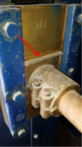
Caption : Transformer front copper pad needs to be unbolted and cleaned.
The solution is to remove all of the bolted joints starting at the welding transformer’s front copper pads. Inspect these joints. If they are just slightly discolored and not showing large areas of melting or high spots, you can clean them with a 3M Scotchbrite pad. The red Scotchbrite pads work the best for this. Do NOT use emery cloth or other abrasives since they will cause grooves in the surface to reduce the available conducting areas.
Once the surfaces are clean, put a coating of silver on both sides of the each joint. A good product for this is Cool-Amp. This is a silver powder that is available from most arc welding supply houses. To use, dip a soft cloth into clean water and then dip into the Cool-Amp powder. Then rub the powder across the surface several times. Let the part set for at least 2 minutes and then buff it with a soft cloth. Repeat layers until you see what looks like a dull silver color.
If the surfaces show arc points are not flat, they will have to be machined professionally. This should only be done if more than 25% of the surface is bad. Use the silver process above when finished.
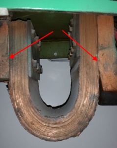
Caption: Typical Laminated Shunt.
Another area to look at is the condition of the shunts. On most welders the secondary current is conducted from the transformer to the upper moving part of the welder through a stack of flexible thin copper sheets called a Laminated Shunt. Over years of use these pieces of copper break off near the fastening points to reduce the number of sheets left for conducting the welding current. If you find that more than 5% of the sheets are broken off, replace the shunts. They are not expensive, and your resistance welding equipment supplier can take the measurements to get an exact, and probably improved, laminated shunt.
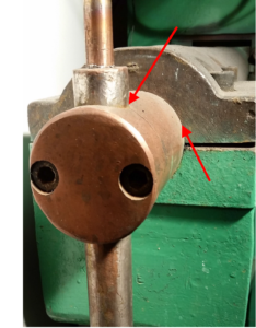
Caption: Check areas where water cooled holders are clamped into the welder arm.
Don’t forget to check the areas where the electrode holders attach to the welder’s arms. It is not unusual to see a holder that has been smashed with a hammer during “adjustment”, and then that portion of rough surface is pushed lower into the arm to conduct electricity. Remove electrode holders and check for smooth and clean surfaces. If the holders are beat up just replace them. The new ones are not very expensive, and you will gain both power as well as eliminate water leakage where the electrode is installed.
Once you do this cleaning and reassembly, the welder will probably put out 20% or more power than it did before the cleaning for the same heat settings.
We have only one spot welding in our plant. It was originally purchased to weld 12 gage channels. We no longer have that job but have recently taken in a new project welding 22 gage steel panels and drawers together.
The problem is that the welder is too large and we have to set our weld heat at about 30% to get a weld that does not send metal out into the aisles. And at this low heat setting our window of good and bad welds is very small. Just a little change in electrode force or weld heat can produce a weld that snaps off without making a good nugget. What can we do?
Unfortunately the “one size fits all” idea does not work well with resistance welders. But here are some ideas.
First see if your welder has a large TAP SWITCH handle. This will be either on the side of the welder, or might be mounted to the welding transformer itself. The TAP SWITCH reduces the secondary voltage of the welding transformer to lower the current. Setting this TAP SWITCH to a lower number will lower the welding current. This should allow you to make better welds on thinner metal by keeping the WELD HEAT % setting no lower than 60%. If you are welding thicker metal and require a WELD HEAT % greater than 90%, turn the TAP SWITCH to a higher number and reset the WELD HEAT %.
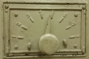
Caption: Use the TAP SWITCH to set the main range of weld heat.
Unfortunately some of the more recent resistance welding machines no longer have tap switches. The transformer manufacturers thought it was a good idea to eliminate these tap switches. It was not!
But you might find that there are internal terminals to lower the secondary voltage in the back wiring compartment of the welding transformer. First, turn off the power going to the welder and lock out the disconnect switch. Then take the back plate off the welding transformer and see if there are some large studs inside. If they are, they will probably be marked with numbers. The lower number will be the lower heat. Just unbolt the wire going to a higher number and move it to a lower number stud.
If your welding transformer does not have these studs and only one heat setting, the only other choice is to operate the welder on a lower line voltage. If the welder is rated at 440-460V, you can connect it to a 220V line if you have one large enough. The welder will now have about ½ the secondary current, and you will be able to set your control to much higher welding heat settings to provide a more robust weld process. The primary current will also be reduced by ½.
Send your comments and questions on resistance welding to:
eliza.weldfabtechtimes@gmail.com


